Dragon Machine Library
Click on the Machine Library option in the Dragon software to set up a new machine, make changes to your current machine, or select which machine you are using for the next job.
Contents
Machine List
- This list will show your machine(s) labeled in the way you have named them.
Action Buttons
- Add New: Click the Add New
 button to add a new machine to the machine list.
- Delete: Click the Delete
 button only if you're sure you would like to delete the machine and its information from the machine list. A warning window will pop up asking if you're absolutely sure of this action. If you need to consult a Bend-Tech staff member before making such a significant change to your software, please do so by calling our office at 651-257-8715.
- Clone: Click the Clone
 button to clone your machine information. This will create a duplicate of the machine you have selected from the machine list.
- Save: Click the Save
 button to save any changes made to your Dragon machine settings or the list to the left.
- Close: Click the Close
 button to close the window after changes have been saved.
Main

Machine Properties

Machine Name:
![]()
- Enter the name of your machine in the Machine Name: field.
Model

- Select the model of the machine you're using in the Model: drop-down menu.
Tubing Capability

- Click on the option that indicates what tube capabilities your Dragon machine came with.
Units

- Click on whether you are working in inches or millimeters.
Machine Calibration
Calibration Wizard

- Click on the Wizard button in the Machine Calibration section to go through the Dragon Calibration.
Basic Settings

Default Process Order
- Default Process Order Box: This box will contain the 3 different processes that will take place in the fabrication process
 (Marking, Engraving, Polyline Cutting and Cutting). To order these in the way you want them, select one from the list and use the Up
  and Down
  arrows to decide the procession.

- Order by Part: Click the "Order by Part"
 option to assign the process order to each individual part.
- Order by Shift: Click the "Order by Shift"
 option to assign the process order to each individual shift.
- Order by Location: Click the "Order by Location"
 option to assign the process order to start at the beginning of the tube in a shift and work its way down the tube's length regardless of the process that is to occur.
Misc Options
- Reposition/Flip between parts: Check this check box if you'd like to have a reposition or flip occur between parts on a nested project.
- Disable Corner IFR: Check this check box to disable the corner inverse feed rate. This is an advanced function that is seldom required to activate. Please leave unchecked unless otherwise instructed by a Bend-Tech technician.
- Post-Cut Dwell: Check the "Post-Cut Dwell"
 check box and add a value into the corresponding field to increase the dwell for every cut by the specified number of seconds.
CAD Settings

- Display Action Directions: Check the Display Action Directions check box and the software will display direction arrows withing the designer and nesting interfaces. This is checked as a default.
- Display Transition Paths: Check the Display Transition Paths
 check box and the software will display the path taken by the machine from action to action.
- Display Jaws: Check the Display Jaws
 checkbox to show the jaws of the chuck in any nesting project.
- Display Dead Zone: Check the Display Dead Zone
 checkbox to show the dead zone (or space of tubing that will not reach to the tool changer) in any nesting project.
Colors
- Click the Display Transition Paths
 to indicate the color of the transition paths as they appear in the software.
- Click the Display Jaws
 to indicate the color of the chuck jaws as they appear in the software.
- Click the Display Dead Zone
 to indicate the color of the dead zone as it appears in the software.
Gate Settings

- For 21" Dragon Machines, checking the "Wait for Gate Open" check box will enable an extended delay in movement of the chuck when it trips the switch for the center gate.
- The value entered into the "Delay Length:" value field will determine the duration of additional time taken for the chuck's pausing. NOTE: A delay value of "0" will cause a program pause which is the default amount of time.
Pause for Drops
- Enable Pausing: Check the "Enable Pausing"
 checkbox to cause the plasma torch to pause when finishing a through-cut or cope. This will ensure a clean cut-off.
- Minimum Length: Enter a value in the "Minimum Length:"
 text field which will determine the minimum length needed before a pause can occur on an end cut.
Large Tube Feed Rate Override
- Size: Enter a value in the Size:
 value field. If the width or height of any square or rectangular tube that is used exceeds this size, the corner cutting feed rate will be reduced to prevent the tube from releasing out of the chuck due to rotational speed.
Tool Settings

Cutting Tool
- Lift Amount (Short): Enter the height of the lift amount for a short distance travel of the plasma head in the "Lift Amount (Short)"
 text field.
- Lift Amount (Long): Enter the height of the lift amount for a long distance travel of the plasma head in the "Lift Amount (Long)"
 text field.
- Shield Width at Bottom Enter a width of your torch's consumable tip in the Shield Width at Bottom
 value field. This setting is used to detect collisions with the torch tip and material.
- Angle of Tip Shield Enter the angle of the torch's consumable tip in the Angle of Tip Shield
 value field. This setting is used to detect collisions with the torch tip and material.
- Use OK to Move Signal Check the Use OK to Move Signal
 check box and the software will use your torch power source settings to determine the wait time for when the torch will ignite. Then, enter a value in the Max Wait Time:
  field (in seconds) for the maximum wait time allowed for the ignite before the signal is not received by the torch. If the wait time exceeds this value, the torch will not ignite and the current running project will be aborted.
Cut Travel Direction
- Right: Click on the "Right"
 option and the cutting direction will always start from the left and move to the right.
- Left: Click on the "Left"
 option and the cutting direction will always start from the right and move to the left.
Engraver Tool:
- Lift Amount (Short): Enter the height of the lift amount for a short distance travel of the engraver head in the "Lift Amount (Short)" text field.
- Lift Amount (Long): Enter the height of the lift amount for a long distance travel of the plasma head in the "Lift Amount (Long)" text field.
Marking Tool:
- Lift Amount (Short): Enter the height of the lift amount for a short distance travel of the engraver head in the "Lift Amount (Short)" text field.
- Lift Amount (Long): Enter the height of the lift amount for a long distance travel of the plasma head in the "Lift Amount (Long)" text field.
Misc Options
- Long Travel Minimum: Enter a value in the "Long Travel Minimum"
 text field to indicate the least amount of distance that the machine will travel to still be considered a 'long travel'. A long travel will most likely be when the machine travels from one set of contours to another, or one end of tubing to another.
- Aux Button Action: Select an option from the Aux Button Action
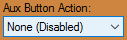 drop down menu to assign that option to the Aux button on the machine operator's panel. When None (Disabled) is selected, there will be no action assigned to the Aux button. When Home All Axes is selected, the machine will home all axes when the Aux button is pushed. When Repeat Part is selected, the machine will repeat the last loaded part when the Aux button is pushed.
Action Settings

Part ID Marking
- Enable Part ID Marking: Check the "Enable Part ID Marking"
 checkbox and your part will be either marked or engraved with the part ID information by default.
- Part ID Font: Click on the "Part ID Font"
 drop down menu to choose the font that the part ID will be marked or engraved in by default.
- Part ID Size: Enter a value in the "Part ID Size"
 text field to designate a size of the part ID lettering. This will be in inches or millimeters depending on what your units of measurement are set to.
- Part ID Location: Enter a value in the "Part ID Location"
 text field to designate a location down the length of the tubing where the part ID will be located by default.
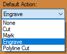
- Default Action: Select the tool you would like the machine to use for your part ID by default.

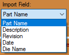
- Import Field: Select the field you would like the machine to use for your part ID by default.

Holesaw Info (Default)
- Enable Holesaw Marking: Check the "Enable Holesaw Marking"
 checkbox and your part will be either marked or engraved with the holesaw information by default.
- Holesaw Font: Click on the "Holesaw Font"
 drop down menu to choose the font that the holesaw information will be marked or engraved in by default.
- Holesaw Size: Enter a value in the "Holesaw Size"
 text field to designate a size of the Holesaw information lettering. This will be in inches or millimeters depending on what your units of measurement are set to.
- Mark: Select the "Mark"
 option if you would like the holesaw information to be marked with a marker by default.
- Engrave: Select the "Engrave"
 option if you would like the holesaw information to be engraved by default.
Bend Marks (Default)
- None: Select the "None"
 option if you would not like the bend marks assigned to an action by default.
- Mark: Select the "Mark" option if you would like the bend marks to be marked with a marker by default.
- Engrave: Select the "Engrave" option if you would like the bend marks to be engraved by default.
- Mark both sides of Bend: Check this check box if you'd like the Dragon machine to mark both tangents of each bend by default.
- Mark First Bend Only: Check this check box if you'd like the Dragon machine to mark only the first bend mark in on each part.
Saddles (Default)
- None: Select the "None" option if you would not like the saddles assigned to an action by default.
- Mark: Select the "Mark" option if you would like the saddles to be marked with a marker by default.
- Engrave: Select the "Engrave" option if you would like the saddles to be engraved by default.
- Cut: Select the "Cut"
 option if you would like the saddles to be cut by default.
End Cuts (Default)
- None: Select the "None" option if you would not like the end cuts assigned to an action by default.
- Cut:' Select the "Cut"
 option if you would like the end cuts to be cut with the machine's plasma cutter by default.
- Mark: Select the "Mark" option if you would like the end cuts to be marked with a marker by default.
Short Leg Override
- None: Select the "None" option if you would like the end cuts assigned to its default action.
- Mark: Select the "Mark" option and an end cut will be marked instead of cut by default. The shortest a leg can be before this override occurs is defined by the Die Limitations within the Die Library.
- Engrave: Select the "Engrave" option and an end cut will be engraved instead of cut by default. The shortest a leg can be before this override occurs is defined by the Die Limitations within the Die Library.
Shift Marks (Default)
- Mark: Select the "Mark" option if you would like the shift marks to be marked with a marker by default.
- Engrave: Select the "Engrave" option if you would like the shift marks to be engraved by default.
Mechanical Settings

***These advanced options should only be altered under the direction of a Bend-Tech support technician.***
Backlash Correction
- Use the Test button to perform a backlash test with your machine
Rectangle Gate Correction
- Use the Calibrate button to enter a calibration wizard to assist with correcting any amount your rectangle front gate might be off-center.
Axis Step Correction
- Use the Calibrate button to adjust the motor tuning of any given axis.
Machine Limit Warnings

"IT IS NOT RECOMMENDED TO ADJUST THESE SETTINGS UNLESS YOU KNOW WHAT YOU'RE DOING"
- Enable X Limits Enter the minimum value allowed for the X travel here. This value can be less than zero (Home Position) but should not exceed the travel limit of the machine.
- Enable Z Limits -Min- Enter the minimum value allowed for the Z travel here. This value can be less than zero (Home Position) but should not exceed the travel limit of the machine. -Max- Enter the maximum value allowed for the Z travel here. This value should not exceed the travel limit of the machine.
- Enable A Limits -Min- Enter the minimum value allowed for the A travel here. This value can be less than zero (Home Position) but should not exceed the travel limit of the machine. -Max- Enter the maximum value allowed for the A travel here. This value should not exceed the travel limit of the machine.
Calibration

"IT IS NOT RECOMMENDED TO ADJUST THESE SETTINGS UNLESS YOU KNOW WHAT YOU'RE DOING"
Factory Settings

"IT IS NOT RECOMMENDED TO ADJUST THESE SETTINGS UNLESS YOU KNOW WHAT YOU'RE DOING OR ARE INSTRUCTED TO MAKE CHANGES BY A BEND-TECH REPRESENTATIVE."