Industrial Guide
"Bend-Tech Industrial comes equipped with all of the functionality available in our SE product along with the following."
Make sure to check out the Industrial product video HERE
Contents
Importing
"NOTE: All parts that are brought into Bend-Tech Industrial must be in either .STEP/.stp or .IGES/.igs format."

1. Choose to import a file from the button on the "Task Menu" screen labeled "Tube Model" ![]() .
.
2. Choose a file to import by using the standard method. Go up to the File menu at the top left hand corner of the screen, select the Import option and choose from either Tube Model (.step/.stp), STEP (.step/.stp) or IGES (.IGES/.igs) from the list depending on which file format you'd like to import.
Defining The Part
Color Code
1. After importing a solid tube model, the part will appear with contoured lines, arcs and circles. These are color coded to help you to identify certain sections of the tubing.

- Blue Lines: Indicate the arcs and circles of the tubing.
- Red Lines: Indicate the straights within the length of tubing.
Material Definition
![]()
1. The Select Material: drop down menu will be grayed out until the user has fully tracked the imported part. Once the part is tracked, it will need to be assigned a material which matches its Defined: outer diameter and wall thickness.
2. If a material is not set up in your material library that will match the imported part, clicking the Plus: ![]() button will add the imported material for you and assign it to the current part or project.
button will add the imported material for you and assign it to the current part or project.

3. The Material: section will show which material is chosen from the Select Material: drop down menu above. The Outside Diameter (OD) of the material will be shown next to the orange icon and the Material Wall Thickness will be shown next to the blue icon.

4. The Defined: section will show which material is applied to the part after importing. The detected Outside Diameter (OD) of the material will be shown next to the orange icon and the detected Material Wall Thickness will be shown next to the blue icon.

5. The number of bends detected in the part will be shown next to this icon.
Below this initial section is the tool box with four tabs labeled Part, Manual Tools, Holes & Cutouts and Saddles.
Part

Define Part
- This section contains the general options for defining a part automatically.

1. For any imported part containing a bend, click on the "Bent" .png) button followed by a single arc/circle (Blue Line) at the end of the tubing in order to track the part automatically. The part will become a 3-D model with material applied to it when it has been successfully tracked.
button followed by a single arc/circle (Blue Line) at the end of the tubing in order to track the part automatically. The part will become a 3-D model with material applied to it when it has been successfully tracked.
2. For any imported straight part, click on the "Straight" .png) button followed by a straight side of the tubing (Red Line), then an arc/circle (Blue Line) at the end of the tubing. NOTE: You may have to The part will become a 3-D model with material applied to it when it has been successfully tracked.
button followed by a straight side of the tubing (Red Line), then an arc/circle (Blue Line) at the end of the tubing. NOTE: You may have to The part will become a 3-D model with material applied to it when it has been successfully tracked.
3. After a single part has been defined with all of it's geometry including end profiles, holes, and saddles, click the "Save Part"  button to save it to the Parts list.
4. To clear your progress and revert the part back to its original solid model form, click the "Clear" .png) button. A window will appear to ensure that you want to confirm the changes.
button. A window will appear to ensure that you want to confirm the changes.
5. Check the "Auto-Track Profile" ![]() check box before defining the part in order to automatically track the contours of the circles, arcs and straight lines. This may need to be unchecked in order to track some difficult contours individually. This will be more time consuming, but necessary at times. It is recommended to leave this checked until there is a conflict in defining the part.
check box before defining the part in order to automatically track the contours of the circles, arcs and straight lines. This may need to be unchecked in order to track some difficult contours individually. This will be more time consuming, but necessary at times. It is recommended to leave this checked until there is a conflict in defining the part.
Define Start Profile
- This section contains the options for defining the interior and exterior edge on the start profile of the tubing.

1. Click on the "Exterior" .png) button followed by the outer arc/circle (Blue Line) at the START of the tubing. NOTE: If the circle at the edge of the tubing is split into smaller arcs, you may have to select multiple arcs along the same path in order to define this exterior circle. If it is Red, it is not complete. If it is Green, the circle has been defined.
button followed by the outer arc/circle (Blue Line) at the START of the tubing. NOTE: If the circle at the edge of the tubing is split into smaller arcs, you may have to select multiple arcs along the same path in order to define this exterior circle. If it is Red, it is not complete. If it is Green, the circle has been defined.
2. Click on the "Interior" .png) button followed by the inner arc/circle (Blue Line) at the START of the tubing. NOTE: If the circle at the edge of the tubing is split into smaller arcs, you may have to select multiple arcs along the same path in order to define this interior circle. If it is Red, it is not complete. If it is Green, the circle has been defined.
button followed by the inner arc/circle (Blue Line) at the START of the tubing. NOTE: If the circle at the edge of the tubing is split into smaller arcs, you may have to select multiple arcs along the same path in order to define this interior circle. If it is Red, it is not complete. If it is Green, the circle has been defined.
3. To clear your progress and revert the part back to before the start profile was defined, click the "Clear" button. A window will appear to ensure that you want to confirm the changes.
Define End Profile
- This section contains the options for defining the interior and exterior edge on the end profile of the tubing.

1. Click on the "Exterior" .png) button followed by the outer arc/circle (Blue Line) at the END of the tubing. NOTE: If the circle at the edge of the tubing is split into smaller arcs, you may have to select multiple arcs along the same path in order to define this exterior circle. If it is Red, it is not complete. If it is Green, the circle has been defined.
button followed by the outer arc/circle (Blue Line) at the END of the tubing. NOTE: If the circle at the edge of the tubing is split into smaller arcs, you may have to select multiple arcs along the same path in order to define this exterior circle. If it is Red, it is not complete. If it is Green, the circle has been defined.
2. Click on the "Interior" .png) button followed by the inner arc/circle (Blue Line) at the END of the tubing. NOTE: If the circle at the edge of the tubing is split into smaller arcs, you may have to select multiple arcs along the same path in order to define this interior circle. If it is Red, it is not complete. If it is Green, the circle has been defined.
button followed by the inner arc/circle (Blue Line) at the END of the tubing. NOTE: If the circle at the edge of the tubing is split into smaller arcs, you may have to select multiple arcs along the same path in order to define this interior circle. If it is Red, it is not complete. If it is Green, the circle has been defined.
3. To clear your progress and revert the part back to before the end profile was defined, click the "Clear" button. A window will appear to ensure that you want to confirm the changes.
Auto Tracking/Cut Tracking/Ignore Lines
![]()
- When the "Auto-Tracking" check box is checked, the definition of a single section will automatically occur when clicking on a single contour.
![]()
- When the "Cut Tracking" check box is checked, the cuts located on the part will define automatically when the tubing is tracked.
![]()
- When the "Ignore Lines" checkbox is checked, enter a length in the "Max Profile Line Length" value field to ensure that contours of a profile track to the intended profile. A longer max line length will include larger lines when assessing the profile.

- When the "Auto Adjust Max Profile Line Length" check box is checked, enter a length in the "Max Profile Line Length" value field to ensure that contours of a square or rectangle profile track to the intended profile. A longer max line length will include larger lines when assessing the profile.
Manual Tools

- Before a part can be fully imported, each section that needs to be included on the part must be defined.
- Before beginning, keep in mind that a section is represented by simple lines and arcs as seen below. This does not represent the part that will be imported. This only defines which sections can be included in the part definition.
- Also, sections are defined based off the centerline. So, for example, if the Two Points tool is used to define a section, the line between those two points will be used to represent the centerline of that section.
Define Straight Section
Two Points
- To define a section using two points, select the "Two Points"
 button. First, click on one pick point. Once the first point is selected, a green wireframe preview of the section will generate from this point. To place the end of this section, select another Pickpoint.

.png)
Circle -> Distance
- To define a section by selecting a circle and any point, select the "Circle -> Distance"
 button. First, select on a circle feature. Once the circle is selected, a green wireframe preview of the section will generate from this point. Next, define the length of the section by choosing a Pickpoint.
.png)
.png)
Line
- To define a section by selecting a line feature, select the "Line"
 button. Next, click on a line feature that will represent the centerline of the section.
.png)
.png)
Define Bend
Two Circles
- To define a bend between two circle features, click the Two Circles
 button. Next, click on the first circle. Once the circle is selected, a green wireframe preview of the section will generate from this point. Then click on another circle to place the section.
.png)
.png)
Center, Start, End
- To define a bend by selecting the center, start, and end points, select the Center, Start, End
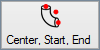 button. Next, click the centerpoint of the bend. This point will be located off the bend, at the center of the arc as if it were a full circle. Then click on the starting point of the arc and lastly, the end point of the arc to place the section.
.png)
Start, Mid, End
- To define a bend by defining the starting point, mid point, and end point, select the Start, Mid, End
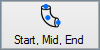 button. First, selecting the centerline start point of the arc, the mid point, and then the centerline end point.
.png)
Arc
- To define a bend by selecting an arc feature, select the "Arc"
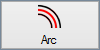 button. Next, select on an arc feature that will represent the centerline of the bend.
.png)
.png)
Two Straights
- To define a bend by selecting the straight lengths on either side, select the "Two Straights"
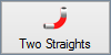 button. Click on the line on one side of the arc, then click on the line on the other side.
.png)
.png)
Reverse Last
- Select the "Reverse Last"
 button to reverse the last bend.

Modify Sections
Extend Straight
- To add or remove length from a straight section of tube, select the "Extend Straight"
 button. Next, click on the section that will be adjusted. Then enter the amount to add or remove (enter as a negative to shorten) and select the "OK" button.

.png)
Remove Section
- To remove a defined section from the part, select the "Remove Section"
 button. Then, just click on a red highlighted section for it to be removed.

.png)
Tools
Delete Feature
- To delete a feature made up of one of the Yellow, Blue, Red, or Green lines/arcs/circles, select the "Delete Feature"
 button. Next, click on the feature that will be deleted.

.png)
Add Line
- To add a new line to the existing part, select the "Add Line"
 button. Then, select a Pickpoint that will indicate the start of the line followed by a pickpoint that will indicate the end of the line.

.png)
Holes & Cutouts

Define Holes/Cutouts
Exterior
- To define holes and cutouts on the part you must first select the "Exterior"
 button followed by the outer arc/circle of the hole you'd like to define. The hole or cutout will turn a teal (off blue/green color) when it has been defined.

.png)
Interior
- Then, select the "Interior"
 button followed by the inner arc/circle of the hole you'd like to define. The hole or cutout will turn a light blue when it has been defined.

.png)
- When your holes/cutouts are defined, green check marks will appear to the left in the list section under the "Outer" and "Inner" labels. Yellow question marks indicate that the "Outer" or "Inner" contours have NOT been defined.
Clear All
- Select the "Clear All"
 button in order to clear all defined contours for the holes/cutouts.
.png)
Saddles

Define Saddles
Exterior
- To define saddles on the part you must first select the "Exterior"
 button followed by the outer arc/contour of the saddle you'd like to define. The saddle will turn a dark yellow color when it has been defined.

Interior
- Then, select the "Interior"
 button followed by the inner arc/contour of the saddle you'd like to define. The saddle will turn a light yellow when it has been defined.

Direction
- Finally, select the "Direction"
 button followed by red line indicating the outer diameter of the intersecting tube profile.
- When your saddles are defined, green check marks will appear to the left in the list section under the "Outer", "Inner" and "Direction" labels. Yellow question marks indicate that the "Outer" or "Inner" contours have NOT been defined.
Clear All
- Select the "Clear All" button in order to clear all defined contours for the saddles.
Open

Define Open Features
Auto-Track
- When the "Auto-Track" option is selected, you can select a contour on an open feature and it will automatically track the feature and add the feature to the list below.
Transferring
- In order to transfer the part, select the "Transfer"
 button from above the display screen in order to transfer the part to a single part designer, Assembly, Dragon CAM etc.
"NOTE: Sending a part to any other designer than Industrial Part will cause your part to lose all contours for notches, holes, and saddles."
Transfer to Industrial Part
- Once a part is transferred to Industrial Part there are five tabs which will help you to alter the part further and prepare it for manufacturing.
Display
.png)
- There are 4 different display viewing options in Industrial Part. These can help you see the part as bent, straight, unfolded and with dimensions.
- Clicking the "Bent Part View"
 will show the part as it will look when finished including bends.
- Clicking the "Straight Part View"
 will show the part as it will look before bending.
- Clicking the "Flat Layout View"
 will show the part as if the tube was folded out and laid flat.
- Clicking the "Dimensions View"
 will show or hide the dimensions of the part including numbers indicating each bend and the Tristar.
Die & Material
.png)
.png)
- If you have not set defaults in the Options menu, you must select a material from the "Select Material" drop down menu. The corresponding Diameter, Wall Thickness and Weight of the material will be shown to the right.
.png)
- You must also assign a die using the "Select Die" drop down menu and the corresponding Achieved CLR, Calibrated CLR and Bend Location Offset will be shown to the right. You can also create a custom CLR with the "Custom CLR"
 button below, and see a detailed list of all your saved dies simply by selecting the "Detailed List"
  button.
![]()
- If have a bender set up in the Machine Library with a material and die attached, you can simply avoid the above steps and pick the "Select Machine"
 button to select your machine from the list.
Part Details
.png)
- The "Part Details" tab will help you keep track of the specific details assigned to your part.
- Click on the "Part Settings"
 button in order to apply changes to the current part. Options include Part Results, Setup Sheets, Unit of Measure, Rotation, Length/Location, and Tolerance.
- Check the "Simple Cut Export"
 check box to ensure that all end cuts on the part are exported when the part is ultimately transferred to Dragon CAM.
- Check the "Simple Hole Export"
 check box to ensure that all holes and cutouts on the part are exported when the part is ultimately transferred to Dragon CAM.
- Use the "Cut-Off Start"
 and "Cut-Off End"
  value fields to add cut-off to either end of the tubing. NOTE: This information will change the bend locations along with the overall length of the part.
- To add notes, type in the "Notes" field below. Any notes shown here will be included on the setup sheet. To set a default note, Select "Options" under the Tools menu and go to the Single Parts tab. If desired, enter any date next to "Date", any revision information next to "Revision" and any description next to "Description".
Display
.png)
- Under the "Display" tab, settings specific to the 3D part display can be adjusted. Select the button below "Part Color" to change the color of the part as it is displayed to the right. Select the button below "Cut-Off Color" to change the color that cut-off lengths will be displayed in. To change the size of the Dimension or Tri-Star text, enter values into either of the Dimension Size or Tri-Star Scale field.
Features to Display (Bent Model)
- Check the box next to Dimensions
 to have the length measurements and markers displayed in the part display.
- Check the box next to Apex Guides
 to to show lines extending from the bend verification points to the part.
- Check the box next to Tri-Star
 to have the XYZ compass/tri-star displayed in the part display.
- Check the box next to Apex Dimensions
 to show the dimensions of the part in Apex mode. (If unchecked, the dimensions will be displayed in Tangent mode.)
- Check the box next to Verification Points
 to show points at the ends of the tubing and numbers located on each bend.
While any of these options are unchecked, they will not be shown in the current 3D part display area.
Tasks
.png)
- Click the "Verify"
 button to check dimensions from all main points of the part. These include tangents and apexes of bends and end points along the entire length of tubing.
.png)
- Click the "Flat Layout"
 button to view dimensions for starts, mids and ends of bends contained in the part and seen in flat layout mode.
.png)
- Click the "Price"
 button to view and alter the price list associated with the current part.
.png)
- Click the "Display XYZ"
 button to view the bending instructions in XYZ form.
.png)
- Click the "Print Scale"
 button to orientate your part onto multiple sheets of paper if you'd like to print out a full size flat layout of your part.
.png)
Manuf. Warning
.png)
- This tab will show if there are any manufacturing warnings with the part which would make it an impossible part to create. A red line above this tab indicates this. A green line above this tab indicates that the part is correct and ready for fabrication.
Industrial Options
.png)
- The Industrial Options window can be found in the TOOLS->OPTIONS menu and contains options for part rotation indicator options, display options, tolerance and exporting options.
Rotational Indicator
"The Rotational Indicator section will allow you to place a Tab, Notch or Mark at the Start or End of your tubing in order to keep track of rotation during cutting and bending."
Type
.png)
- The None option in the type section will ensure that there is no rotational indicator placed on the tubing.
- The Tab option in the type section will place a square or triangular tab on the start or end of your tubing in order to keep track of rotation.
- The Notch option in the type section will place a square or triangular notch on the start or end of your tubing in order to keep track of rotation.
- The Mark option in the type section will place a lined mark on the start, end or along the tube in order to keep track of rotation.
Tab/Notch Shape

.png)
- When the type is set to Tab, select either the Square or Triangle option to indicate the shape of the tab.
- When the type is set to Notch, select either the Square or Triangle option to indicate the shape of the notch.
Dimensions

.png)
- When the type is set to Tab, you are given options to enter the Length, Rotation Offset and Width of the tab.
- When the type is set to Notch, you are given options to enter the Length, Rotation Offset and Width of the notch.
- When the type is set to Mark, you are given the options to enter the Length, Rotation Offset and Distance from End of the mark.
Which Side

- When either the Tab, Notch or Mark options are selected, you will be given the option to place the rotational indicator at the Start or End of the tubing.
Precision / Tolerance

These tolerances may be altered due to conflicting polyline resolution values. This will occur when the project is sent to nesting and the polyline resolution will take precedent.'
- The Precision (Geometry) field is where you can set the tolerance for how small or far away a feature can be from another in order to be defined or be considered as a part of the part as a whole.
- The Precision (Comparison) field is where you can set the tolerance for comparing two features to be identical or separate entities.
- The Bend Mark Text Resolution: field is where you can set the image resolution of your bend mark text as it appears on the unfolded tubing.
Export Options

- Check the Always Export Cut Profile (.dxf) check box if you'd like your cut profiles exported along with any .dxf file that you export.
- Check the Simple Cut Export (.step/.iges) check box if you'd like simple cuts to be exported along with any .stp/.igs file that you export.
- Check the Simple Hole Export (.step/.iges) check box if you'd like simple holes to be exported along with any .stp/.igs file that you export.
Polyline Resolution

- The Max Length: field is where you will set the maximum length of a polyline segment that will be converted to a larger line. Think of this a a cap/boundary on the length of your contours. The higher the length value, the less resolution your part will achieve. This will determine the efficiency and precision of your contours.
- The Max Angle: field is where you will set the maximum inside angle between polyline segments that will be converted to a single line. If the angle between two connecting line segments is a lesser angle than the max angle value entered, the connecting lines will not convert. The higher the angle, the less resolution your part will achieve. This will determine the efficiency and precision of your contours.
- The Max Offset: field is where you will set a maximum offset on either side of your contours. If a converted line that is created crosses outside the bounds of this offset, polylines will not be converted to a larger segment and remain as they are. The higher the offset value, the less resolution your part will achieve. This will determine the efficiency and precision of your contours.
Draw Colors
.png)
- The Tube/Part color is set to gray by default.
- The Start Profile colors are set to dark green and light green by default. Dark green indicates the inner contour of the start profile while the light green indicates the outer contour of the start profile.
- The End Profile colors are set to dark blue and light blue by default. Dark blue indicates the inner contour of the end profile while the light blue indicates the outer contour of the end profile.
- The Holes colors are set to teal and cyan by default. Teal indicates the inner contour of the hole while the cyan indicates the outer contour of the hole.
- The Saddles color is set to gold by default.
Misc Options
.png)
- Check the Normal Cuts (Perpendicular Cutting) check box and your cuts will be converted to become located at the perp of the bend it is assigned to.
- Check the Auto-Tack Cut Profiles check box and your cut profiles will automatically be tracked when a new part is imported.
- The Default Stock Length: field is where you will enter a value (in inches or millimeters: depending on your setup) for your default stock length of tubing as it appears when you open a nesting project.
- The Default Web Size: field is where you will enter a value (in inches or millimeters: depending on your setup) for your default web size between cuts when creating a nesting project.
- The Saddle Scale Factor: field is where you will enter a value (1=100%) for your saddle scale factor.
"We appreciate you taking your time to read through this guide thoroughly. Tutorials on Industrial can be found on our YouTube channel. Thank you."