Making a 180 Degree Bend in XYZ
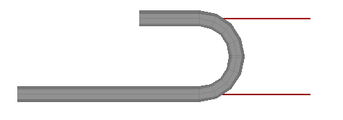
The XYZ part interface uses "Apex" as the default for entering in locations for bends. What do we do in the case of a 180 degree bend which doesn't have an apex because the 2 edges are parallel?
In this example, we will show you three methods for creating a 180 degree bend in the XYZ interface.
NOTE: All XYZ locations are based upon a 0,0,0 global location. Which means that each location is referenced to an absolute location. The start point does NOT need to be 0,0,0.
Using Two 90 Degree Bends:
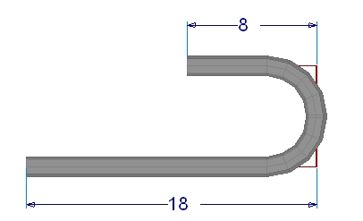
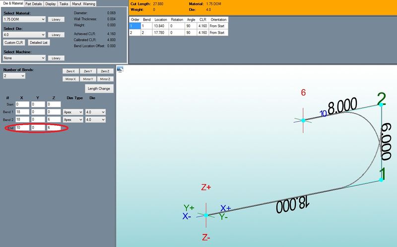
The final bent part will look like this:
In order to create a 180 degree bend using apex bends it will require two 90 degree bends.
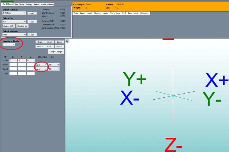
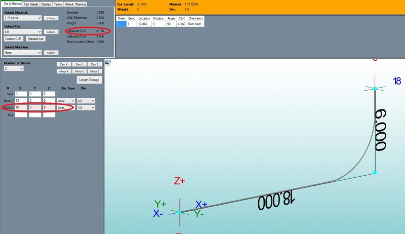
1) Set the "Number of Bends" to "2" and leave both set to "apex" in the "Dim Type" column.
2) Zero out the "Start" row to make our start point the center of the locator.
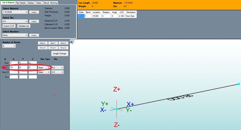
3) In the "Bend 1'" row enter "18" for "X", and "0" for both "Y" and "Z". - This will give us 18" from the start of the tube, to the apex of the first bend.
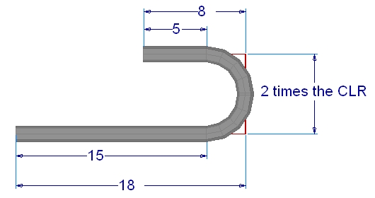
4) In the "Bend 2" row enter "18" for "X", "0" for "Y", and "6" for "Z". - This will take us from the first apex, to the second apex. The 6 is equal to twice our CLR (3 X 2 = 6).
5) In the "End" row enter "10" for "X", "0" for "Y", and "6" for "Z" - This will take us from the second apex, to the end of the tube.
NOTE: You will need to remember to run the bend 180 degrees and ignore the 2nd bend line from the results window.
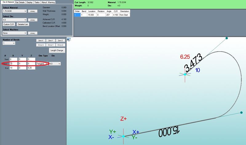
Using the Tangent Method:
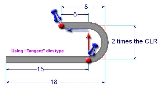
Using this method we only need one tangent bend instead of two apex bends. We will need to subtract the CLR from our values, so our 18 becomes 15 (rounding the CLR to 3 for simplicity).
The next feature location is in reference to the start of the bend as shown in the following picture.
1) Leave the "Number of Bends" at "1" and change it to "tangent" in the "Dim Type" column.
2) Zero out the "Start" row to make our start point the center of the locater as in the first example.
3) In the "Bend 1" row enter "15" for "X", and "0" for both "Y" and "Z".
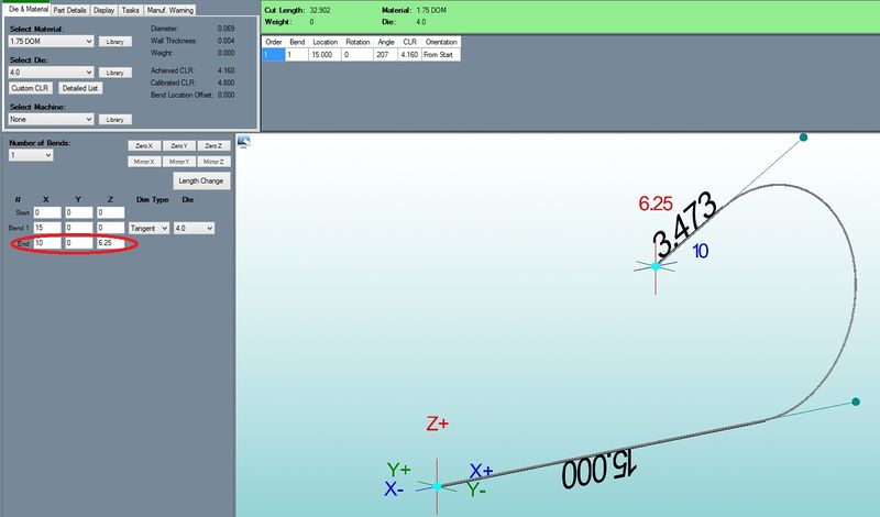
4) In the "End" row enter "10" for "X", "0" for "Y", and "6.25" for "Z".
 Using the Perpendicular Method
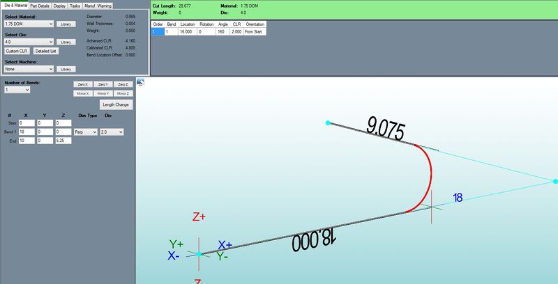
The perpendicular point is located at the apex of the first 90 degrees (or the tangent + the CLR). It is entered into Bend-Tech in a similar fashion as the tangent method, but it is not necessary to subtract the CLR.
1) Leave the "Number of Bends" at "1", but change the value in the "Dim Type" column to "perp".
2) Zero out the "Start" row to make our start point the center of the locator.
3) Enter the following values to create the 180.
