Difference between revisions of "Dragon"
(→Point) |
(→Line) |
||
| Line 167: | Line 167: | ||
<div tabindex="0" class="usermessage mw-customtoggle-myLine mw-customtoggle" style="background-color: #CC6600; border: solid 1px #CC6600;">Click here for Line functions.</div> | <div tabindex="0" class="usermessage mw-customtoggle-myLine mw-customtoggle" style="background-color: #CC6600; border: solid 1px #CC6600;">Click here for Line functions.</div> | ||
<ul class="mw-collapsible mw-collapsed" id="mw-customcollapsible-myLine"> | <ul class="mw-collapsible mw-collapsed" id="mw-customcollapsible-myLine"> | ||
| − | <li style="display: list-item;">[[File: | + | <li style="display: list-item;">[[File:Dragon_Line_Options1.png|right]] |
'''Two Points:''' Select the "'''Two Points'''" option, click on a point in the display area and it will turn into a blue circle. Now click on a second point to create a line between the two points. Enable Continuous mode by clicking the "'''Continuous'''" checkbox. This will automatically start new lines with the first point set as the end of the last line. To stop drawing lines while in Continuous mode click "'''Cancel'''" in the "'''Activity'''" section.</li> | '''Two Points:''' Select the "'''Two Points'''" option, click on a point in the display area and it will turn into a blue circle. Now click on a second point to create a line between the two points. Enable Continuous mode by clicking the "'''Continuous'''" checkbox. This will automatically start new lines with the first point set as the end of the last line. To stop drawing lines while in Continuous mode click "'''Cancel'''" in the "'''Activity'''" section.</li> | ||
<li style="display: list-item;">'''Horizontal:''' Select the "'''Horizontal'''" option and set the length of the line by entering a value in the "'''Line Length:'''" field to create a horizontal line. Place the line by clicking a point in the display area. The mid-point of the line will be centered on the point you select.</li> | <li style="display: list-item;">'''Horizontal:''' Select the "'''Horizontal'''" option and set the length of the line by entering a value in the "'''Line Length:'''" field to create a horizontal line. Place the line by clicking a point in the display area. The mid-point of the line will be centered on the point you select.</li> | ||
Revision as of 12:33, 12 October 2015
"UNDER CONSTRUCTION:THANK YOU FOR YOUR PATIENCE."
- Our Bend-Tech Dragon software works alongside with Bend-Tech Industrial and is meant to prep the part(s) or project before production using the Dragon machine.
- The "Dragon Task Menu" consists of 3 options for creating new parts. Bend-Tech Dragon will also allow transfers from Bend-Tech Industrial and other designers.
.png)
Bent Part
.png)
.png)
- Clicking on this option will allow the user to create a new "Custom Part" including bends and end cuts. It has many of the same characteristics of our "Custom Part" designer, except with a few additions that users will need in order to add copes or mitered cuts on the ends of the tubing.
Action Tabs
Die & Material
- The "Die & Material" section is where users will select the die which will be assigned to bend the part and the material associated with that die.
.png)
- The Select Material:"
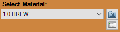 drop down menu is where users will choose their desired material.
.png)
- The "Select Die:"
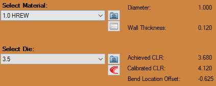 drop down menu is where users will choose their desired die.
.png)
- The section to the right of these drop down menus will show the information associated to the current die and material.
Cut Start / Cut End
The "Cut Start" tab will determine the cuts on the starting of the tube, while the "Cut End" tab will determine the cuts on the ending of the tube.
.png)
.png)
- The "Type of Cut" section gives users the option to choose a type of cut from "None", "Coping (Fishmouth)" and "Miter".
- The "Intersecting Tube:" drop down menu will give users the option to choose the size of tube that the current part will be intersecting with. This will adjust the size of the end cope(s) or miter cut profile(s).
- Checking the "Knifed Edge" check box will cause the coped or mitered cuts to appear as if they are cut flush to the intersecting tube.
- Checking the "Display Cross Tube" check box will cause the intersecting cross tube to appear in the display screen.
- Used only when the "Cut Type" is set to "Coping (Fishmouth)" or "Miter", the degree of rotation entered into the "Rotation:" field will determine the rotation of the cut on either the start or end of the tube.
- Used only when the "Cut Type" is set to "Coping (Fishmouth)" or "Miter", the degree of angle entered into the "Angle:" field will determine the angle of the cut on either the start or end of the tube.
- The value entered into the "Cut-Off:" field will determine how many extra units (inches or millimeters) of tubing will be added to the start or end of the tube.
- Used only when the "Cut Type" is set to "Coping (Fishmouth)", the value entered into the "Offset:" field will determine how the intersecting tube is offset from the start or end of the tube.
Manuf. Warning
The "Manufacturing Warning" tab will show the user if the part that was created is or isn't a valid part ready for production.
.png)
.png) button at the top of the screen. To learn more about this interface, scroll down to the "Custom Design" section of this Wiki.
button at the top of the screen. To learn more about this interface, scroll down to the "Custom Design" section of this Wiki..png) button.
button.Straight Part
.png)
.png)
- Clicking on this option will allow the user to create a straight part with either flat, coped or mitered end cuts. This option will also let the user account for rotation, angles and offsets for the tube ends.
Select Material:
1. The "Select Material:" drop down menu is where users will choose their desired material.
Type of Cut
2. The "Type of Cut (Start / End)" sections give users the option to choose a type of cut from "None", "Coping (Fishmouth)" and "Miter".
Intersecting Tube
3. The "Intersecting Tube:" drop down menu will give users the option to choose the size of tube that the current part will be intersecting with. This will adjust the size of the end cope(s) or miter cut profile(s).
Knifed Edge
4. Checking the "Knifed Edge" check box will cause the coped or mitered cuts to appear as if they are cut flush to the intersecting tube.
Tube Length:
5. The value entered into the "Tube Length:" field will determine the overall length of the part.
Rotation:
6. Used only when the "Cut Type" is set to "Coping (Fishmouth)" or "Miter", the degree of rotation entered into the "Rotation:" field will determine the rotational offset of the cuts on the tube. When the "Counter-clockwise" check box is checked, the rotation of the part will change counter-clockwise based on the rotational amount entered.
Angle:
7. Used only when the "Cut Type" is set to "Coping (Fishmouth)" or "Miter", the degree of angle entered into the "Angle:" field will determine the angle of the cut on either the start or end of the tube.
Offset:
8. Used only when the "Cut Type" is set to "Coping (Fishmouth)", the value entered into the "Offset:" field will determine how the intersecting tube is offset from the start or end of the tube.
Display Screen
9. The "Display Screen" is where your current part will be shown. Click the "Home" button in the upper left hand corner to return the part to its original view.
Cancel
10. The "Cancel" button will close the window and you will lose any information applied to the designed part.
OK
11. The "OK" button will send the part shown to Dragon's flat layout mode known as "Custom Design".
button.Quick Nest
.png)
.png)
Clicking on this option will give you the ability to nest multiple length parts together in order to accommodate the stock length of tubing you are working with.
Select Material:
1. The "Select Material:" drop down menu is where users will choose their desired material. To the right, the material information will be shown.
Stock Length:
2. The "Stock Length:" field is where users will enter the stock length of their material (in inches or millimeters based on the units of measurement specified in the "Options" menu).
Needed Lengths:
3. The "Needed Lengths:" section is where users will enter the values of their part lengths and quantities of each. These can be added by selecting the "Add" button below this section.
Add
4. Clicking the "Add" button will allow another line to be added to the "Needed Lengths:" section.
Remove
5. Clicking the "Remove" button will remove a line from the "Needed Lengths:" section.
Cancel
6. Clicking the "Cancel" button will close the simple nesting window and you will lose any progress made in this window.
OK
7. Clicking the "OK" button will send the "Needed Lengths:" to the "Dragon Nesting" interface where users will be able to view the lengths nested along their stock length of tubing. Editing can also be done there as well.
Custom Design
.png)
Action Tabs
Part Data
- The "Part Data" tab shows current material, cut length, full bending instructions, options to change the bend order, add cut-off and personal dates and notes associated with the current part.
.png)
- The Material
 that is applied to the part is shown in the upper left hand corner of the tab.
- The Cut Length
 for the part is shown in the upper right hand corner of the tab.
- The Bending Instructions
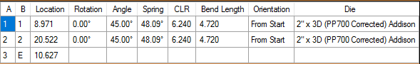 section will show you the bend number, bend location, rotation, angle, spring angle, CLR and orientation for the current part.
.png)
- The "Bend Order"
 button will open the bending simulation and will allow the user to manipulate the part for bending only. Please see our Bend Order Tutorial in order to learn more.
.png)
- The "Reverse Tube"
 button will reverse all of the geometry of the part including copes, bend locations, text, holes, etc.
.png)
- The "Cut-Off Start:" and "Cut-Off End:"
 text fields are where users can input values to add cut-off to either end of the tubing.
- The "Date:"
 text field is where users can input a design date or fabrication date.
- The "Part ID:"
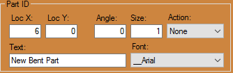 text field is where users can input a part identification name or number.
.png)
- The "Notes:"
 text field is where users can input any notes specific to the current part.
.png)
Create Geometry
Point
- Cursor: Select the "Cursor" option and pick anywhere on the screen to click and place a point. The point will be placed at the exact location of your cursor and will not reference any other entities while being placed. The point will not be highlighted blue before placement.

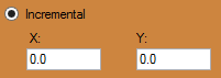
- Incremental: Select the "Incremental" function, provide X and Y coordinates into the "X:" and "Y:" value fields and select a reference point in the display area. X is the horizontal distance and Y is the vertical distance from the reference point. (Note: A negative (-) X value will place the point to the left of the reference point. A negative (-) Y value will place the point below the reference point.) The point will be highlighted in blue while the reference point is being chosen.
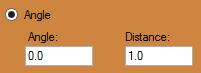
- Angle: Select the "Angle" option under the point tab, enter the distance from the reference point in the "Distance" field and enter an angle in the "Angle" field. If the "Angle" field is set to 0°, the new point will be created directly to the right of the reference point. To place the new point, click on a point to use as a reference point. The point will be highlighted in blue while the reference point is being chosen.
- Absolute: Select the "Absolute" option and enter X and Y coordinates into the "X:" and "Y:" fields and click the "Submit"
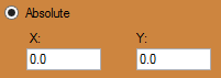
 button to place the point. The reference point will always be (0,0) (or the origin that shows X and Y in the display area).
 - Intersection: Select the "Intersection" option followed by two intersecting lines in order to place a point at the intersection of the two lines.
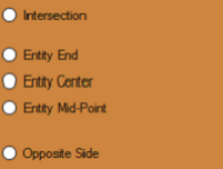
- Entity End: Select the "Entity End" option followed by an object or line in the display area to place an end point of that object. The point will be placed at the end that you click closest to. The point will be highlighted in blue before the object is chosen.
- Entity Center: Select the "Entity Center" option followed by an object or line in the display area to place a center point on that object. The point will be placed directly in the center of the object highlighted. The point will be highlighted in blue and the point will be visible before the object is chosen. (Note: This option is not meant to find the center of self-created objects like flanges, but rather lines, arcs, text, tabs, slots along with holes).
- Entity Mid-Point: Select the "Entity Mid-Point" option followed by an object or line in the display area to place a mid-point on that object. The point will be placed directly in the center of the section of the object highlighted. The point will be highlighted in blue and the point will be visible before the object is chosen. (Note: This option is not meant to find the center of self-created objects like flanges, but rather lines, arcs, text, tabs, slots along with holes).


Line
- Two Points: Select the "Two Points" option, click on a point in the display area and it will turn into a blue circle. Now click on a second point to create a line between the two points. Enable Continuous mode by clicking the "Continuous" checkbox. This will automatically start new lines with the first point set as the end of the last line. To stop drawing lines while in Continuous mode click "Cancel" in the "Activity" section.
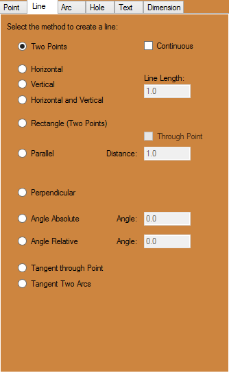
- Horizontal: Select the "Horizontal" option and set the length of the line by entering a value in the "Line Length:" field to create a horizontal line. Place the line by clicking a point in the display area. The mid-point of the line will be centered on the point you select.
- Vertical: Select the "Vertical" option and set the length of the line by entering a value in the "Line Length:" field to create a vertical line. Place the line by clicking a point in the display area. The mid-point of the line will be centered on the point you select.
- Horizontal and Vertical: Select the "Horizontal and Vertical" option to create two intersecting lines of equal length and set the line lengths using the "Line Length:" field. Click on a point to place the lines. Both lines will be placed with the intersection directly over the point you select.
- Rectangle: Select the "Rectangle (Two Points)" option, click a point in the display area and creating a point will cause it to turn into a blue circle. A blue rectangle will be drawn between the selected point and the point nearest the cursor. Move the cursor near the intended second point and make sure the blue rectangle is correct. Click to create the rectangle.
- Parallel: Select "Parallel" so you can either enter the distance between the parallel line and the reference line or use the "Through Point" feature. If a distance is entered and the Through Point checkbox is not selected, click a line to set it as the reference line. After picking the reference line, select which side the parallel line will be placed on by clicking on that side of the reference line. If the Through Point checkbox is selected you must first select a reference line, followed by a point that the parallel line will pass through.
- Perpendicular: Select the "Perpendicular" option to create a line perpendicular to previously established line. Set the length of the perpendicular line using the "Line Length:" field. Then, click a line in the display area to set it as the reference line. The side you click on will determine the direction of the line. Click on any point to place the perpendicular line there.
- Angle Absolute: Select the "Angle Absolute" option to create a line in the display area with a desired angle. First, enter the desired length in the "Line Length:" field and the desired angle in the "Angle:" field. Click on a point to place the Line there.
- Angle Relative: Select the "Angle Relative" option and enter the length of the desired line in the "Line Length:" field and the relative angle in the "Angle:" field. Click on a line to use as a reference line and click on a point to use as a starting point for the new line. The angle of the line will be the sum of the angle of the reference line and the value entered in the Angle field.
- Tangent through Point: Select the "Tangent through Point" option to create a line connected to an arc by clicking near the side of the arc that the line will be drawn to. Click on a point away from the arc to create the line.
- Tangent Two Arcs: Select the "Tangent Two Acrs" option to add a line between two arcs by clicking near the side that the line will be drawn to. Select a second arc to create a line that attaches to the tangent of that arc.
- Notches: Select the "Notches" option and which type of notch you would like to add by clicking either "Chamfer, Corner, or Edge". If adding a Chamfer or Corner, input the desired depth into the "Depth:" field. To add the notch, click on a line and another line that you want the notch to connect to. On the second line, the location that is selected determines which direction the notch faces. Click on the end closest to the direction you want it to face. To add an Edge, you need to input both the Depth and Width. This will create a rectangle with the depth and width that you selected which can be added to the edge of a line. The edge will be added to the closest line and will be placed on the nearest end. An edge can be added to either side of the end of a line by clicking on that side. Check the Auto-Trim box to automatically cut off any part of a line that extends past a notch.

Arc
- Fillet: Select the "Fillet" option and input the desired radius of the filleted arc into the "Radius:" field. Click on the first line, which will turn blue. A blue arc will come off the first line and connect with whatever line is nearest to the cursor. Change the direction of the fillet by moving the cursor to the other side of the first line. Click to place the fillet. If the "Auto-Trim" checkbox is checked, any part of either line that extends past the fillet will be cut off.
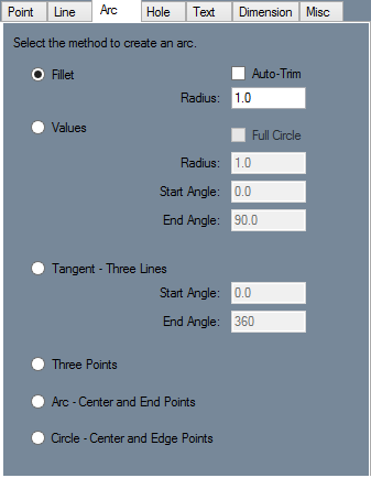
- Values: Select the "Values" option and input the "Radius:, Start Angle:, and End Angle:" of the arc into their respective fields. Click on a point to place the arc with its center directly over that point. Check the "Full Circle" checkbox to automatically set the start angle at "0" and the end angle at "360", creating a full circle.
- Tangent - Three Lines: Select the "Tangent - Three Lines" option and set the start and end angle of the arc using the "Start Angle:" and "End Angle:" fields. Click on three lines within the part, in any order, to create an arc that uses those three lines as tangent lines.
- Three Points: Select the "Three Points" option and pick three points that lie within the desired arc. The first and third points will be end-points. The second point will be on the arc and will define the radius of the arc. If the first and third points are the same point, a circle will be drawn between the first and second point.
- Arc - Center and End Points: Select the "Arc - Center and End Points" option and click on the point that will lie in the center of the intended arc. Click on another point to create the first end point. A blue arc will be drawn from the first end point to the point on the arc closest to the cursor. Move the cursor until the second end point is in the desired location and click to place the arc.
- Circle - Center and Edge Points: Select the "Circle - Center and Edge Points" option and click on a point to set it as the center point. A blue circle will be drawn with a radius equal to the distance to the point nearest to the cursor. Move the cursor to the desired point and click to place the circle.

Hole
- Hole Shape
- Round: Select Round, enter a diameter in the Diameter field, and click on a flange to place a round hole at that point.
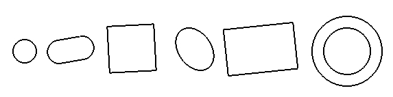
- Oval: Select Oval, enter a width and length in the Width and Length field, and enter an angle for the hole in the Angle field. Click on a PickPoint or endpoint to place an oval hole at that point.
- Square: Select Square, enter a width in the width field, and enter an angle for the hole in the Angle field. If you want to automatically round the corners of the square, you can enter a value in the Corner Radius field. Entering 0 in the Corner Radius field will result in square corners. Click on a PickPoint or endpoint to place an oval hole at that point.
- Ellipse: Select Ellipse and click on the Length button. A window will appear with a diagram of a cylinder going through a plate. You must enter the width and angle of this cylinder in the Diameter of Cylinder and Angle of Cylinder fields. The length of the hole will be calculated automatically. Click the Copy button, close the window, and paste the value into the Length field by clicking in the field and hitting the Control key and the "V" key at the same time. Enter the same width and angle that you used before and click on a point to place an elliptical hole at that location.
- Rectangle: Select Rectangle and enter a width and height in the Width and Height fields. Enter an angle in the Angle field and click on a point to place a rectangular hole at that location.
- Dimple: A dimple is a round hole that is slightly raised, so that the plate around the edges of the hole slope up towards the hole. The Inner Diameter is the section that will actually be cut out of the plate. The Outer Diameter is the area of plate surrounding the hole that slants up towards the hole. Enter an inner and outer diameter and a height in the respective fields. Select Up or Down in order to set whether the dimple is raised or pressed into the plate. Click on a point to place a dimple at that location.

Text
- Creating Text
- Normal: Click the "New Text" button and type the text that you want in the "Text Properties" text field. Select a font using the "Font Family:" drop down menu and enter a size factor in the "Font Size:" value field. Enter the angle of the intended text in the "Text Angle:" field. Use the "Alignment:" drop down menu to set the text alignment and use the "Line Spacing:" drop down menu to set the spacing between lines of text.
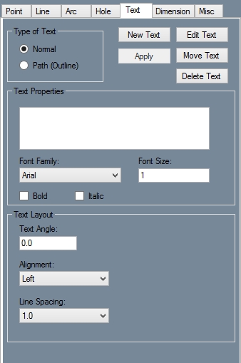
- Path (Outline): When using Path (Outline) to create text, any text you place will be constructed out of lines and arcs which can be used as if they were user placed lines and arcs. The Text Properties area is the same as if you were creating normal text, however the Text Layout area is different. In the Text Angle field enter an angle for the text to be placed at. Enter the spacing between each letter in the Letter Spacing field. To Stretch the string of text horizontally, enter an amount to stretch by in the Horizontal Stretch field. Use the Style drop down menu to choose whether the text is straight or curved. If it is curved up or down, you can enter the radius of the arc that the text is curved around in the Arc Radius field. Use the Precision drop down menu to select the level of detail that the text is drawn with. If you want to create curved but keep each individual letter upright, check the Static Letter Angles checkbox.
- Editing Text
- Edit: To edit an existing string of text, click on the Edit button and click on a previously placed piece of text. Make any changes to the Text Properties and Text Layout areas and click the Apply button.
- Move: To move text, click the move button and click on a string of text. Click on a point to place the text at that location.
- Delete: To delete text, click on the Delete button and click on a string of text.

Dimension
- Create
- Horizontal: Click the Horizontal button and click two points in the display window. A Dimension, along with dimension and extension lines, will appear and move with the cursor. Move the Dimension to the desired location using the cursor and click to place it.
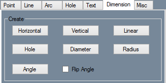
- Vertical: Click the Vertical button and click two points in the display window. A Dimension, along with dimension and extension lines, will appear and move with the cursor. Move the Dimension to the desired location using the cursor and click to place it.
- Linear: Click the Linear button and click two points in the display window. A Dimension, along with dimension and extension lines, will appear and move with the cursor. Move the Dimension to the desired location using the cursor and click to place it.
- Hole: Click the Hole button and click on a hole. The radius of the hole, along with an abbreviated version of the name of its shape, will be drawn and bound to the cursor. Move the cursor until the dimension is in the desired location and click to place it.
- Diameter: Click on the Diameter button. Click on a circle in the display window. A dimension and dimension line will appear in the circle and be bound to the cursor. If the cursor is moved out of the circle an extension line will be drawn in between the circle and the dimension. Move the cursor to reposition the dimension and click to place it.
- Radius: Click the Radius button and click an arc. The radius of the arc, along with a dimension, will be drawn and bound to the cursor. Move the cursor until the dimension is in the desired location and click to place it.
- Angle: Click the Angle button. Click the outside point of the first line. See the picture to the right for an example of outside and inside points. Your points can be endpoints of a line or individual points. Click the inside point of the first line. Now click the outside and inside points of the second line. The dimension, as well as a dimension arc and two extension lines, will be bound to the cursor. Move the cursor until the dimension is in the desired location and click to place it. To measure the reverse of the angle, click the "Flip Angle" checkbox.
- Edit
- Move: Click on the Move button and click on a dimension. The dimension will now move with the mouse and can be repositioned. Click to place the dimension.
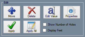
- Delete: Click on the Delete button and click on a dimension to delete it.
- Edit Value: Click on Edit Value and click on a dimension. A window will pop up and ask for a new display value for the dimension. Enter a value and click on the OK button.
- Properties: Click on the "Properties" button and click on a dimension. Make any necessary changes to the settings by clicking in the value field. Standoff, Offset, Text Size, Arrow Width, and Arrow Height can all be changed by typing a new value to replace the existing value. Arrow Type, Distance Tolerance, and Angle Tolerance can be changed by using the drop down menus that appear when their value boxes are clicked. Dim Color, Ext Color, and Text Color can be changed by clicking on their value boxes and selecting the desired color in the color window that appears. To update the dimension with the new settings click on the "Apply:" button.
- Apply: Click on the "Properties:" button and click on a dimension. Make all necessary changes to the dimensions settings. Click Apply to apply the settings to the dimension.
- Apply All: Make any necessary changes to the settings and click on the Apply All button. All dimensions will be updated with these settings.
- Show Number of Holes: Click on this checkbox to display the number of similar holes when creating hole dimensions.
- Display Feet: Click on this checkbox to display feet and inches rather than exclusively inches.
- Setting
- Standoff: Click on the box next to Standoff in the value field and enter a new value to replace the existing one. Use the "Properties:" and "Apply:" buttons to update a single dimension with the new value, or use "Apply All:" to update all dimensions.
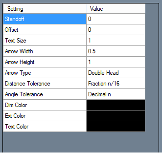
- Offset: Click on the box next to Offset in the value field and enter a new value to replace the existing one. Use the "Properties:" and "Apply:" buttons to update a single dimension with the new value, or use "Apply All:" to update all dimensions.
- Text Size: Click on the box next to Text Size in the value field and enter a new value to replace the existing one. Use the "Properties:" and "Apply:" buttons to update a single dimension with the new value, or use "Apply to All:" to update all dimensions.
- Arrow Width: Click on the box next to Arrow Width in the value field and enter a new value to replace the existing one. Use the "Properties:" and "Apply:" buttons to update a single dimension with the new value, or use "Apply All:" to update all dimensions.
- Arrow Height: Click on the box next to Arrow Height in the value field and enter a new value to replace the existing one. Use the "Properties:" and "Apply:" buttons to update a single dimension with the new value, or use "Apply All:" to update all dimensions.
- Arrow Type: Click on the box next to Arrow Type in the value field and select an option from the drop down menu. Use the "Properties:" and "Apply:" buttons to update a single dimension with the new value, or use "Apply All:" to update all dimensions.
- Distance Tolerance: Click on the box next to Distance Tolerance in the value field and select an option from the drop down menu. Use the "Properties:" and "Apply:" buttons to update a single dimension with the new value, or use "Apply All:" to update all dimensions.
- Angle Tolerance: Click on the box next to Angle Tolerance in the value field and select an option from the drop down menu. Use the "Properties:" and "Apply:" buttons to update a single dimension with the new value, or use "Apply All:" to update all dimensions.
- Dim Color: Click on the box next to Dim Color in the value field. A window will appear where a new color can be chosen. Click on a color and click "OK:". To learn how to define custom colors see the Color page. Use the "Properties:" and "Apply:" buttons to update a single dimension with the new value, or use "Apply All:" to update all dimensions.
- Ext Color: Click on the box next to Ext Color in the value field. A window will appear where a new color can be chosen. Click on a color and click "OK:". To learn how to define custom colors see the Color page. Use the "Properties:" and "Apply:" buttons to update a single dimension with the new value, or use "Apply All:" to update all dimensions.
- Text Color: Click on the box next to Text Color in the value field. A window will appear where a new color can be chosen. Click on a color and click "OK:". To learn how to define custom colors see the Color page. Use the "Properties:" and "Apply:" buttons to update a single dimension with the new value, or use "Apply All:" to update all dimensions.


