Difference between revisions of "Die Library"
(Created page with "'''Bend-Tech 7x Wiki :: Main Menu Bar :: Tools :: Die Library''' right|500px '''View/Edit''': To view and/or edit a die's in...") |
|||
| (32 intermediate revisions by the same user not shown) | |||
| Line 1: | Line 1: | ||
'''[[Main Page|Bend-Tech 7x Wiki]] :: [[Main Menu Bar]] :: [[Tools]] :: Die Library''' | '''[[Main Page|Bend-Tech 7x Wiki]] :: [[Main Menu Bar]] :: [[Tools]] :: Die Library''' | ||
| + | |||
| + | |||
| + | *The '''Die Library''' stores any and all dies available that the user may need to bend parts. | ||
| + | |||
| + | |||
| + | '''To access the die library''', select the '''Tools''' menu and select the '''Die Library''' option in the drop down menu or select the '''Die Library''' option on the [[Task Menu]]. | ||
[[File:die_library_1.png|right|500px]] | [[File:die_library_1.png|right|500px]] | ||
| − | |||
| − | ''' | + | [[File:die_library_2.png|left|150px]] |
| + | |||
| + | *Each die is assigned a set of attributes such as name, achieved CLR, calibrated CLR, minimum distance before a bend, minimum start length, minimum end length, minimum distance between bends with and without rotation, and specific user defined attributes. | ||
| + | |||
| + | |||
| + | |||
| + | *Each die can be calibrated using the [[Calibration|Calibrating]] function where there is a list of predefined dies from a number of different bender models. | ||
| + | |||
| + | |||
| + | |||
| + | *On the left side of the die library window there is a list of all dies saved by the user. The add and delete buttons are located below this list. On the right side of this list there are attributes of the currently selected die. The import and save buttons are situated below the attribute fields. | ||
| + | |||
| + | |||
| + | |||
| + | |||
| + | |||
| + | |||
| + | |||
| + | [[File:die_library_4.png|right]] | ||
| + | |||
| + | |||
| + | <h3>Die Details</h3> | ||
| + | |||
| + | *'''Die Name:''' The name given to the die. This will be the what the die is called throughout the software. It is recommended to give each a unique, descriptive name to more easily identify each die. | ||
| + | |||
| + | |||
| + | *'''Achieved CLR:''' The CLR that the die will actually produce when bending. This value compensates for spring-back and other factors that contribute to inaccuracies in the CLR of a bend. | ||
| + | |||
| + | |||
| + | *'''Calibrated CLR:''' This is a value that is generated and used by the software to ensure accuracy. In general, this value should be 5 to 20% larger than the achieved CLR (''the actual CLR that the die will produce''). '''To get this value, the [[Calibration|calibration wizard]] or the [[OEM Die List]] must be used'''. | ||
| + | |||
| + | |||
| + | *'''Bend Location Offset:''' The offset distance between the mark on the tube and the actual starting point of the bend. For example, if the bend offset is 0, the bend starts exactly where the mark is placed. | ||
| + | |||
| + | |||
| + | *'''Units:''' Die specifications can be given in either inches or millimeters. | ||
| + | |||
| + | |||
| + | *'''SpringBack:''' Multiple springback entries can be added to each die. See the '''[[SpringBack Library]]''' page for more detailed information. | ||
| + | |||
| + | |||
| + | *'''Worksheet:''' The '''Worksheet''' button [[File:worksheet.png]] can be used to calibrate the current die. See the '''Calibration''' page for more information on how this tool works. | ||
| + | |||
| + | |||
| + | *'''OEM List:''' The OEM list contains a variety of dies and their specifications for different machines. See the '''[[OEM Die List]]''' section for more specific information. | ||
| + | |||
| + | |||
| + | |||
| + | |||
| + | [[File:die_library_5.png|right]] | ||
| + | <h3>Die Limitations - Minimum Distances</h3> | ||
| + | If necessary/known, limitations can be added to the selected die. | ||
| + | |||
| + | |||
| + | *'''Start End:''' This is the shortest amount of tube length allowed at the very beginning of the tube before the first bend. This measurement will start at the starting end of the tube and end at the start of the first bend when the bend is as close to the starting edge as possible. | ||
| + | |||
| + | |||
| + | *'''Far End:''' This is the shortest amount of tube length allowed at the end of the tube after the last bend. The measurement will begin at the ending edge of the last bend and end at the end of the tube when the bend is as close to the end of the tube as possible. | ||
| + | |||
| + | |||
| + | *'''Between Bends - with rotation:'''This is the shortest amount of tube length allowed between bends that have rotation. For example, the distance allowed between two bends with a 180° between them. | ||
| + | |||
| + | |||
| + | *'''Between Bends - without rotation:''' This is the shortest amount of tube length allowed between bends that have no rotation. | ||
| + | |||
| + | |||
| + | |||
| + | |||
| + | |||
| + | [[File:die_library_6.png|right]] | ||
| + | <h3>User Defined Definitions</h3> | ||
| + | Users can also create and define custom die attributes. To create a new definition, click on the '''Setup''' [[File:setup_button.png]] button and enter the names of the definitions into the fields provided. Up to seven different definitions can be created. | ||
| + | |||
| + | These definitions and fields will be generated in the User Defined Definitions area for each die in the die library. | ||
| + | |||
| + | |||
| + | |||
| + | |||
| + | |||
| + | <h3>Add Die</h3> | ||
| + | |||
| + | :<h4>Manual Entry</h4> | ||
| + | |||
| + | To manually add a die to the die library, click the '''Add New''' button [[File:add_die.png]] below the die list. After this button is clicked, all the attribute fields will be available to enter data into. Once all the required details are provided, click the '''Save''' button [[File:save_die.png]] to add the die to the library. | ||
| − | |||
| − | + | [[File:die_library_7.png|right|500px]] | |
| + | :<h4>OEM List</h4> | ||
| + | First click the '''OEM List''' button. [[File:oem_list.png]] This will open up a new window (seen to the right) where dies for specific machine makes and models can be searched for and added to the die library. | ||
| + | A list of all the dies currently in the library will be shown on the left side of the window. In the middle there will be a machine/bend drop down menu and a selection menu where the material shape and measurement can be chosen. Below the menus, the die information will be shown once a die is selected from the right die list. To the far right, a list of available dies for the machine and material will be shown once a machine is selected. | ||
| + | '''The die shape and unit of measure''' of the dies shown in the OEM list can be adjusted using the '''Units''' and '''Die Type''' menus. | ||
| + | '''To add a single die from the OEM list''', select a machine from the machine drop down menu and specify the units and die type. Once this is done, a list of dies for the current machine will be generated in the list to right. Click the upper '''Add''' button and the die will be brought into the die library. You will be given the option to change the name of this die, otherwise the name used to identify it in the OEM list will be used (this can be edited later on as well). Click the '''OK''' button to finalize the add. | ||
| + | '''To add multiple dies from the OEM list''', select a machine from the drop down menu and specify the units and die type. Once this is done, a list of dies for the current machine will be generated in the OEM die list to right. Click the lower '''Add''' button to add every die shown in the OEM die list to the die library. All of the dies will keep their original names initially, but can be edited once added to the die library | ||
| + | '''To view the die's attribute information''', click on it to select it. The die details will be generated in the Die Details section between the die lists. | ||
| − | + | [[File:die_library_9.png|right|500px]] | |
| + | :<h4>Import</h4> | ||
| − | + | Die libraries from previous versions of the software can be imported into the current die library. To do so, a valid '''die library.txt''' must be located on the desktop of the computer being used to run the software. If done correctly, the import library window will open when the '''Import''' button [[File:import_library.png]] is clicked. On the left side, there will be a list of the current dies in the die library. On the right, a list of dies from the imported library will be shown. | |
| − | |||
| − | ''' | + | '''To add a die''', select a die in the Imported Library list by clicking on it and then hitting the '''Add''' button. [[File:add_import.png]] Click the '''OK''' button to finalize. |
| − | |||
| + | '''To add all dies''', click the '''Add All''' button. [[File:add_all_import.png]] Every die from the Imported Library list will be added to the current die library. Click the '''OK''' button to finalize. | ||
| − | |||
| − | + | '''To remove a recently imported die''', select the die from the Current Library list and click the '''Remove''' button. [[File:remove_import.png]] | |
| − | |||
| − | |||
| − | |||
| − | |||
| − | |||
| − | + | <h3>Remove Die</h3> | |
| − | ''' | + | '''To remove a die from the die library''', select a die in the die list and click the '''Delete''' button. [[File:delete_die.png]] |
Latest revision as of 09:50, 19 May 2016
Bend-Tech 7x Wiki :: Main Menu Bar :: Tools :: Die Library
- The Die Library stores any and all dies available that the user may need to bend parts.
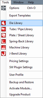
To access the die library, select the Tools menu and select the Die Library option in the drop down menu or select the Die Library option on the Task Menu.
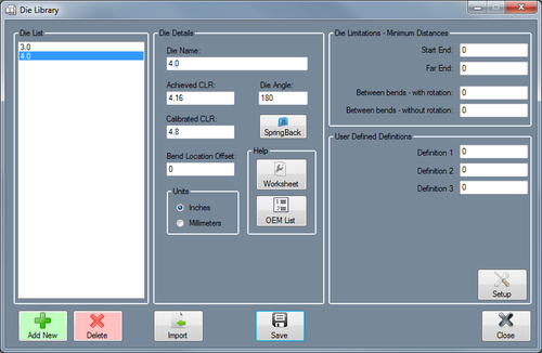
- Each die is assigned a set of attributes such as name, achieved CLR, calibrated CLR, minimum distance before a bend, minimum start length, minimum end length, minimum distance between bends with and without rotation, and specific user defined attributes.
- Each die can be calibrated using the Calibrating function where there is a list of predefined dies from a number of different bender models.
- On the left side of the die library window there is a list of all dies saved by the user. The add and delete buttons are located below this list. On the right side of this list there are attributes of the currently selected die. The import and save buttons are situated below the attribute fields.
Contents
Die Details
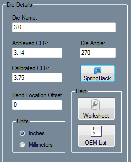
- Die Name: The name given to the die. This will be the what the die is called throughout the software. It is recommended to give each a unique, descriptive name to more easily identify each die.
- Achieved CLR: The CLR that the die will actually produce when bending. This value compensates for spring-back and other factors that contribute to inaccuracies in the CLR of a bend.
- Calibrated CLR: This is a value that is generated and used by the software to ensure accuracy. In general, this value should be 5 to 20% larger than the achieved CLR (the actual CLR that the die will produce). To get this value, the calibration wizard or the OEM Die List must be used.
- Bend Location Offset: The offset distance between the mark on the tube and the actual starting point of the bend. For example, if the bend offset is 0, the bend starts exactly where the mark is placed.
- Units: Die specifications can be given in either inches or millimeters.
- SpringBack: Multiple springback entries can be added to each die. See the SpringBack Library page for more detailed information.
- Worksheet: The Worksheet button
 can be used to calibrate the current die. See the Calibration page for more information on how this tool works.
- OEM List: The OEM list contains a variety of dies and their specifications for different machines. See the OEM Die List section for more specific information.
Die Limitations - Minimum Distances
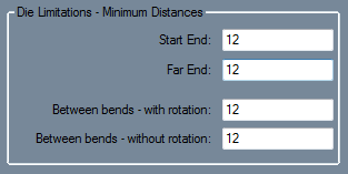
If necessary/known, limitations can be added to the selected die.
- Start End: This is the shortest amount of tube length allowed at the very beginning of the tube before the first bend. This measurement will start at the starting end of the tube and end at the start of the first bend when the bend is as close to the starting edge as possible.
- Far End: This is the shortest amount of tube length allowed at the end of the tube after the last bend. The measurement will begin at the ending edge of the last bend and end at the end of the tube when the bend is as close to the end of the tube as possible.
- Between Bends - with rotation:This is the shortest amount of tube length allowed between bends that have rotation. For example, the distance allowed between two bends with a 180° between them.
- Between Bends - without rotation: This is the shortest amount of tube length allowed between bends that have no rotation.
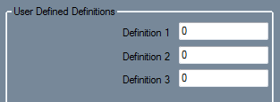
User Defined Definitions
Users can also create and define custom die attributes. To create a new definition, click on the Setup ![]() button and enter the names of the definitions into the fields provided. Up to seven different definitions can be created.
button and enter the names of the definitions into the fields provided. Up to seven different definitions can be created.
These definitions and fields will be generated in the User Defined Definitions area for each die in the die library.
Add Die
Manual Entry
To manually add a die to the die library, click the Add New button ![]() below the die list. After this button is clicked, all the attribute fields will be available to enter data into. Once all the required details are provided, click the Save button
below the die list. After this button is clicked, all the attribute fields will be available to enter data into. Once all the required details are provided, click the Save button ![]() to add the die to the library.
to add the die to the library.
OEM List
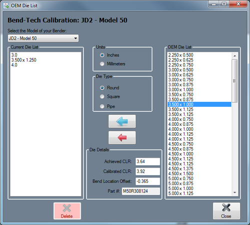
First click the OEM List button. ![]() This will open up a new window (seen to the right) where dies for specific machine makes and models can be searched for and added to the die library.
This will open up a new window (seen to the right) where dies for specific machine makes and models can be searched for and added to the die library.
A list of all the dies currently in the library will be shown on the left side of the window. In the middle there will be a machine/bend drop down menu and a selection menu where the material shape and measurement can be chosen. Below the menus, the die information will be shown once a die is selected from the right die list. To the far right, a list of available dies for the machine and material will be shown once a machine is selected.
The die shape and unit of measure of the dies shown in the OEM list can be adjusted using the Units and Die Type menus.
To add a single die from the OEM list, select a machine from the machine drop down menu and specify the units and die type. Once this is done, a list of dies for the current machine will be generated in the list to right. Click the upper Add button and the die will be brought into the die library. You will be given the option to change the name of this die, otherwise the name used to identify it in the OEM list will be used (this can be edited later on as well). Click the OK button to finalize the add.
To add multiple dies from the OEM list, select a machine from the drop down menu and specify the units and die type. Once this is done, a list of dies for the current machine will be generated in the OEM die list to right. Click the lower Add button to add every die shown in the OEM die list to the die library. All of the dies will keep their original names initially, but can be edited once added to the die library
To view the die's attribute information, click on it to select it. The die details will be generated in the Die Details section between the die lists.
Import
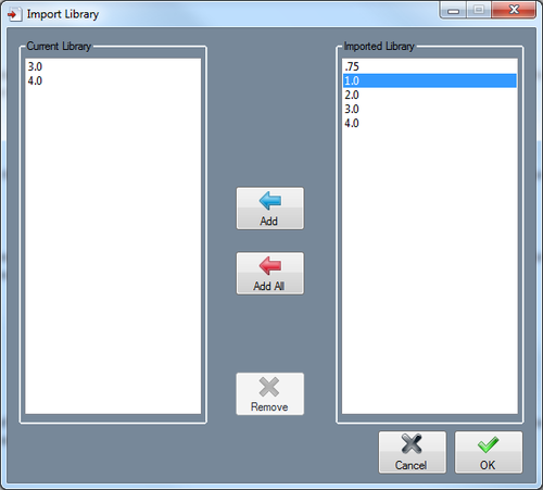
Die libraries from previous versions of the software can be imported into the current die library. To do so, a valid die library.txt must be located on the desktop of the computer being used to run the software. If done correctly, the import library window will open when the Import button ![]() is clicked. On the left side, there will be a list of the current dies in the die library. On the right, a list of dies from the imported library will be shown.
is clicked. On the left side, there will be a list of the current dies in the die library. On the right, a list of dies from the imported library will be shown.
To add a die, select a die in the Imported Library list by clicking on it and then hitting the Add button. ![]() Click the OK button to finalize.
Click the OK button to finalize.
To add all dies, click the Add All button. ![]() Every die from the Imported Library list will be added to the current die library. Click the OK button to finalize.
Every die from the Imported Library list will be added to the current die library. Click the OK button to finalize.
To remove a recently imported die, select the die from the Current Library list and click the Remove button. ![]()
Remove Die
To remove a die from the die library, select a die in the die list and click the Delete button. ![]()
