Exhaust Module
"UNDER CONSTRUCTION: THANK YOU FOR YOUR PATIENCE"
Bend-Tech 7x Wiki :: Exhaust Designer
- The Bend-Tech Exhaust Designer is a stand alone product which can also be an add-on module to owners of Bend-Tech 7x PRO and SE. It assists users in the design and manufacturing of exhaust pipe and tubing. New features include tabs to create mufflers, axles, cubes and cylinders to help create a mock up setting where users can design the exhaust pipes they need.
- This interface does NOT use PickPonts, but offers a 3D space with a grid to design on.
Selection
To create a Exhaust Design Part:
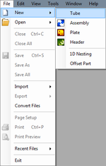
1.) Click the New Tube icon and select the Exhaust option in the Create New menu.
...OR
2.) Select the Exhaust ![]() option from the Task Menu that appears when the software starts up, when all designs are closed, or through the view menu.
option from the Task Menu that appears when the software starts up, when all designs are closed, or through the view menu.
Grid
Grid
Spacing:
- Type in a value between 1 and 50 to adjust how small or large the grid increments are in the display area.
Offset:
- Type in a positive or negative number in the value field to raise or lower the offset from the grid plane in the display area.
Width:
- Type in the value field to increase or decrease the width of the grid.
Length:
- Type in the value field to increase or decrease the length of the grid.
Set Base
- Select the "Set Base"
 button to assign where the center of the grid will be placed. (Note) This can only be done after a part has been designed in the display area.
Pipe / Tubing Path
New Section
- Select the "New Section"
 button to place a length of pipe along the grid in the display area using the two-click method.
Delete
Offset
Choose the style of the offset:
- The Offset Wizard window will open and prompt you to choose an offset with 3 or 4 bends.
Enter the location of the offset:
- Type in the location of the offset in the "Distance to Center" value field. Select whether the distance will be from the start or end of the selected part.
Enter the size of the offset:
- Type in the size of the horizontal offset in the "Horizontal Offset:" value field.
- Type in the size of the vertical offset in the "Vertical Offset:" value field.
Enter the size/location of the offset:
- Type in the distance from the start of the selected section to the beginning (tangent) of the first bend in the "Distance to Start" value field.
- Type in the distance from the start of the section to the ending (tangent) of the last bend in the "Distance to End" value field.
====Enter the length of the offset:==== (For use with 4 bends only)
- Type in the length of the offset in the "Length:" value field.
Select the die for each bend:
- Select the dies for each of the 3 or 4 bends that are to be created by picking them from their drop down menus.
- Select the "Cancel"
 button to cancel the offset or select the "OK" File:OK button.png button to continue with the creation of the offset.


