Dragon A400 Machine Library
Click on the Machine Library option in the Dragon software to set up a new machine, make changes to your current machine, or select which machine you are using for the next job.
Contents
Machine List
- This list will show your machine(s) labeled in the way you have named them.
- The Factory Calibrated Machine will be cloned upon first use of the software and the clone will be used after a Torch Calibration has been performed for it. The Factory Calibrated Machine is there for your reference and cannot be altered or deleted from the list.

Action Buttons
- Add New: Click the Add New
 button to add a new machine to the machine list.
- Delete: Click the Delete
 button only if you're sure you would like to delete the machine and its information from the machine list. A warning window will pop up asking if you're absolutely sure of this action. If you need to consult a Bend-Tech staff member before making such a significant change to your software, please do so by calling our office at 651-257-8715.
- Clone: Click the Clone
 button to clone your machine information. This will create a duplicate of the machine you have selected from the machine list.
- Save: Click the Save
 button to save any changes made to your Dragon machine settings or the list to the left.
- Close: Click the Close
 button to close the window after changes have been saved.
Main

Machine Properties

Machine Name:
![]()
- Enter the name of your machine in the Machine Name: field.
Model

- Select the model of the machine you're using in the Model: drop-down menu.
Units

- Click on whether you are working in inches or millimeters.
Tubing Capability

- Click on the option that indicates what tube capabilities your Dragon machine came with.
Machine Calibration
Calibration Wizard

- Click on the Wizard button in the Machine Calibration section to go through the Dragon A400 Calibration.
Basic Settings

Default Process Order
- Default Process Order Box: This box will contain the 3 different processes that will take place in the fabrication process
 (Marking, Engraving, Polyline Cutting and Cutting). To order these in the way you want them, select one from the list and use the Up
  and Down
  arrows to decide the procession.

- Order by Part: Click the "Order by Part"
 option to assign the process order to each individual part.
- Order by Shift: Click the "Order by Shift"
 option to assign the process order to each individual shift.
- Order by Location: Click the "Order by Location"
 option to assign the process order to start at the beginning of the tube in a shift and work its way down the tube's length regardless of the process that is to occur.
CAD Settings

- Display Action Directions: Check the Display Action Directions check box and the software will display direction arrows withing the designer and nesting interfaces. This is checked as a default.
- Display Transition Paths: Check the Display Transition Paths
 check box and the software will display the path taken by the machine from action to action.
- Display Jaws: Check the Display Jaws
 checkbox to show the jaws of the chuck in any nesting project.
- Display Dead Zone: Check the Display Dead Zone
 checkbox to show the dead zone (or space of tubing that will not reach to the tool changer) in any nesting project.
Colors
- Click the Display Transition Paths
 to indicate the color of the transition paths as they appear in the software.
- Click the Display Jaws
 to indicate the color of the chuck jaws as they appear in the software.
- Click the Display Dead Zone
 to indicate the color of the dead zone as it appears in the software.
Post-Cut Dwell

- Enable Post-Cut Dwell: Check the "Enable Post-Cut Dwell" check box and add a value into the corresponding field to increase the dwell for every cut by the specified number of seconds.
Lifter Trigger Pause

- Enable Lifter Pause: Check the "Enable Lifter Pause:" check box and add a value into the corresponding field to increase the amount of seconds that the chuck trolley pauses to wait for the lifter arm to engage or disengage.
Pause for Drops

- Enable Pausing: Check the "Enable Pausing" checkbox to cause the plasma torch to pause when finishing a through-cut or cope. This will ensure a clean cut-off.
- Minimum Length: Enter a value in the "Minimum Length:" text field which will determine the minimum length needed before a pause can occur on an end cut.
Corner Feed Mode

- Inverse Time Feed Rate: Check this option to choose the corner inverse time feed rate. This is an advanced function that is seldom required to activate. Please leave this option checked unless otherwise instructed by a Bend-Tech technician.
- Machine Travel Rate: Check this option to cause the machine to use the mechanical travel distance to calculate speeds for the corners of the material. Not Recommended.
- Adjusted Feed Rate: Check this option to cause the machine to use the feed rate that has been adjusted for corner surface distance when processing actions on the corners of the material.
Tools

Cutting Tool
- Lift Amount (Short): Enter the height of the lift amount for a short distance travel of the plasma head in the "Lift Amount (Short)"
 text field.
- Lift Amount (Long): Enter the height of the lift amount for a long distance travel of the plasma head in the "Lift Amount (Long)"
 text field.
- Shield Width at Bottom Enter a width of your torch's consumable tip in the Shield Width at Bottom
 value field. This setting is used to detect collisions with the torch tip and material.
- Use OK to Move Signal Check the Use OK to Move Signal
 check box and the software will use your torch power source settings to determine the wait time for when the torch will ignite. Then, enter a value in the Max Wait Time:
  field (in seconds) for the maximum wait time allowed for the ignite before the signal is not received by the torch. If the wait time exceeds this value, the torch will not ignite and the current running project will be aborted.
Cut Travel Direction
- Right: Click on the "Right"
 option and the cutting direction will always start from the left and move to the right.
- Left: Click on the "Left"
 option and the cutting direction will always start from the right and move to the left.
Engraver Tool:
- Lift Amount (Short): Enter the height of the lift amount for a short distance travel of the engraver head in the "Lift Amount (Short)" text field.
- Lift Amount (Long): Enter the height of the lift amount for a long distance travel of the plasma head in the "Lift Amount (Long)" text field.
- Engage Dwell: Enter the time (in seconds) into the "Engage Dwell"
 text field and the machine will wait that amount of time to perform its engraving action so that the engraver can become fully extended.
- Disengage Dwell: Enter the time (in seconds) into the "Disengage Dwell"
 text field and the machine will wait that amount of time to perform a new action after an engraver action has been completed.
Marking Tool:
- Lift Amount (Short): Enter the height of the lift amount for a short distance travel of the tool head in the "Lift Amount (Short)" text field.
- Lift Amount (Long): Enter the height of the lift amount for a long distance travel of the tool head in the "Lift Amount (Long)" text field.
Corner Sharpening Fix
- Corner Sharpening Fix: was intended to give the user added functionality to fix holes which had corners that were rounded-off. This function is no longer used as new bug fixes have been added to software versions 1.08.06 and above.
Misc Options
- Long Travel Minimum: Enter a value in the "Long Travel Minimum"
 text field to indicate the least amount of distance that the machine will travel to still be considered a 'long travel'. A long travel will most likely be when the machine travels from one set of contours to another, or one end of tubing to another.
- Aux Button Action: Select an option from the Aux Button Action
 drop down menu to assign that option to the Aux button on the machine operator's panel. When None (Disabled) is selected, there will be no action assigned to the Aux button. When Home All Axes is selected, the machine will home all axes when the Aux button is pushed. When Repeat Part is selected, the machine will repeat the last loaded part when the Aux button is pushed.
Action Settings

Part ID Marking
- Default Action: Select the tool you would like the machine to use for your part ID by default.
 Your part will be either marked or engraved with the part ID information. This can also be set to none in the case that you don't want your Part ID placed on the part.
- Font: Click on the "Font"
 drop down menu to choose the font that the part ID will be marked or engraved with by default. Our single line fonts are located at the top of this list and are preceded by two underscores to let you know that they are our created fonts.
- Font Size: Enter a value in the "Font Size"
 text field to designate a size of the part ID lettering. This will be in inches or millimeters depending on what your units of measurement are set to.
- Location: Enter a value in the "Location"
 text field to designate a location down the length of the tubing where the part ID will be located by default.
- Rotation Value: Enter a value in the "Rotation Value"
 text field to designate a rotational degree distance that the part ID name will be located around the circumference of the tubing.
- In the drop down field below, you can choose Rotation As Perimeter to cause your rotation value to be read in a length distance around the tube's circumference (in inches or mms depending on your global units of measurement), or you can choose Rotation As Angle to cause your rotation value to be read in degrees around the tube's circumference.
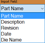
- Import Field: Select the field you would like the machine to use for your part ID by default.

Holesaw Marking
- Default Action: Choose the "Default Action" for how your part will be either marked or engraved with the holesaw information by default.
- Font: Click on the "Font" drop down menu to choose the font that the holesaw information will be marked or engraved in by default.
- Font Size: Enter a value in the "Font Size" text field to designate a size of the Holesaw information lettering. This will be in inches or millimeters depending on what your units of measurement are set to.
Bend Marking
- Default Action: Choose the "Default Action" for how your part will be either marked or engraved with the bend mark information by default.
- Mark both sides of Bend: Check this option if you'd like the Dragon machine to mark both tangents of each bend by default.
- Mark First Bend Only: Check this option if you'd like the Dragon machine to mark only the first bend mark in on each part.
Default Action Types
End Cuts:
- End Cuts:
 Select the action that will be the default action for end cuts. Typically you will never need to change this from the Cut option.
Saddles:
- Saddles:
 Select the action that will be the default action for saddles (or profiles indicating where an intersecting tube\pipe will meet up with the current part). Typically users have this set to mark with a marker, or engrave for a more accurate saddle mark.
Shift Marks:
- Shift Marks:
 Select the action that will be the default action for shift marks (used when the machine needs to make a mark on the tube/pipe for repositioning the chuck trolley, or administering a flip). Typically users have this set to mark with a marker, or engrave for a more accurate shift mark.
Short Leg Override:
- Short Leg Override:
 Select the action that will be the default action for a cutting profile that is within or too close to a bend. The assigned action here will cause the machine to either mark or engrave the cutting profile so that the tube can still fit in the tube bender. The mark can then be used as a guide after bending so the user can either use a notcher or hand torch to apply the cut.
NOTE: The Short Let Override is determined by the user's Die Limitations entered into the Die Library for the die in use.
Mechanical Settings

***These advanced options should only be altered under the direction of a Bend-Tech support technician.***
Backlash Correction
- Use the Test button to perform a backlash test with your machine. This testing is done on each Dragon A400 machine before it leaves the Bend-Tech facility. In the case that the user loses these settings, they should refer to their Factory Calibrated Machine settings to replace these value fields with the original values. In the case that additional backlash testing becomes necessary, this series of tests will attempt to move the selected axis back and forth very quickly at the specified amount. The goal is to find the minimum value that will cause the axis to actually move (not vibrate).
Rectangle Gate Correction
- For use with the Dragon A150 machine only: Use the Calibrate button to enter a calibration wizard to assist with correcting any amount your rectangle front gate might be off-center.
Axis Step Correction
- Use the Calibrate button to adjust the motor tuning of any given axis.
Machine Limit Warnings

"IT IS NOT RECOMMENDED TO ADJUST THESE SETTINGS UNLESS YOU KNOW WHAT YOU'RE DOING"
- Enable X Limits -Min- Enter the minimum value allowed for the X travel here. This value can be less than zero (Home Position) but should not exceed the travel limit of the machine.
- Enable Z Limits -Min- Enter the minimum value allowed for the Z travel here. This value can be less than zero (Home Position) but should not exceed the travel limit of the machine. -Max- Enter the maximum value allowed for the Z travel here. This value should not exceed the travel limit of the machine.
- Enable A Limits -Min- Enter the minimum value allowed for the A travel here. This value can be less than zero (Home Position) but should not exceed the travel limit of the machine. -Max- Enter the maximum value allowed for the A travel here. This value should not exceed the travel limit of the machine.
- Enable B Limits -Min- Enter the minimum value allowed for the B travel here. This value can be less that zero (Home Position) but should not exceed the travel limit of the machine. -Max- Enter the maximum value allowed for the B travel here. This value should not exceed the travel limit of the machine.
Misc Options
- Disable Quick Rewind:
 Check this option and the machine will not use the 'Quick Rewind' function which unwinds the chuck's rotation while moving the machine to loading position. This should be checked on all Dragon A150 Round only machines.
- Disable Dwell Fix:
 Check this option and the machine will not add a dwell fix to the exported G-code for the Dragon. This should be unchecked for most Dragon Machine setups. It is only necessary to uncheck this box if the software is not applying a dwell time for piercing the material.
Calibration

"IT IS NOT RECOMMENDED TO ADJUST THESE SETTINGS UNLESS YOU KNOW WHAT YOU'RE DOING"
Factory Settings

"IT IS NOT RECOMMENDED TO ADJUST THESE SETTINGS UNLESS YOU KNOW WHAT YOU'RE DOING OR ARE INSTRUCTED TO MAKE CHANGES BY A BEND-TECH REPRESENTATIVE."