Bend-Tech SE Software is a must-have if your job, business, or livelihood depends on part bending tube, pipe, rod, wire, and bar. SE has the tools that will allow you to be productive no matter what problems you face in your tube bending fabrication.
Bend-Tech SE Software has extra tools that you will need when you are concerned about setup and production times. What separates SE from the rest is its focus on manufacturability and flexibility in design.
Powerful reverse engineering feature. dxf/step/iges/ interfacing (with the Import/Export function).
Allows for unit conversion (inches vs millimeters).
Focus on Manufacturability
Verify sufficient material is available for the bending process.
Provides a “spring back” bend angles.
Provides extra checking tools to verify part validity.
Allows for multiple dies to be used on the same part.
Extra functionality for roll bending.
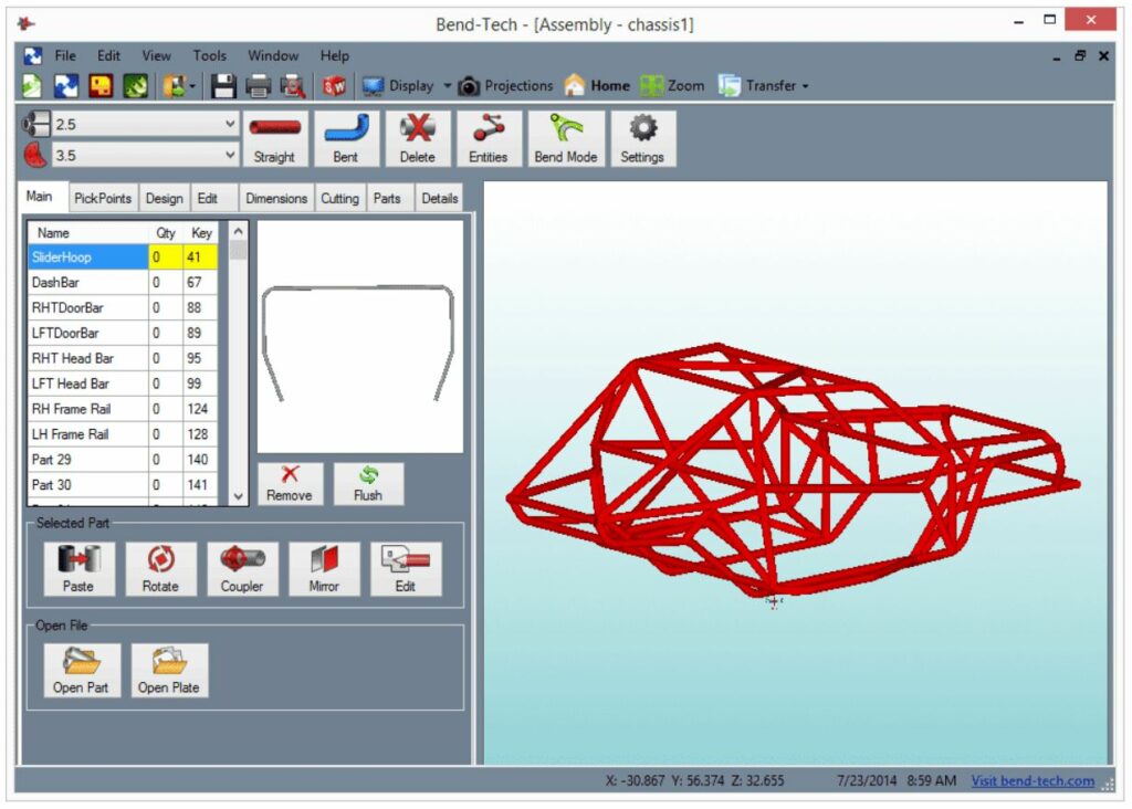
Graphical layout interface.
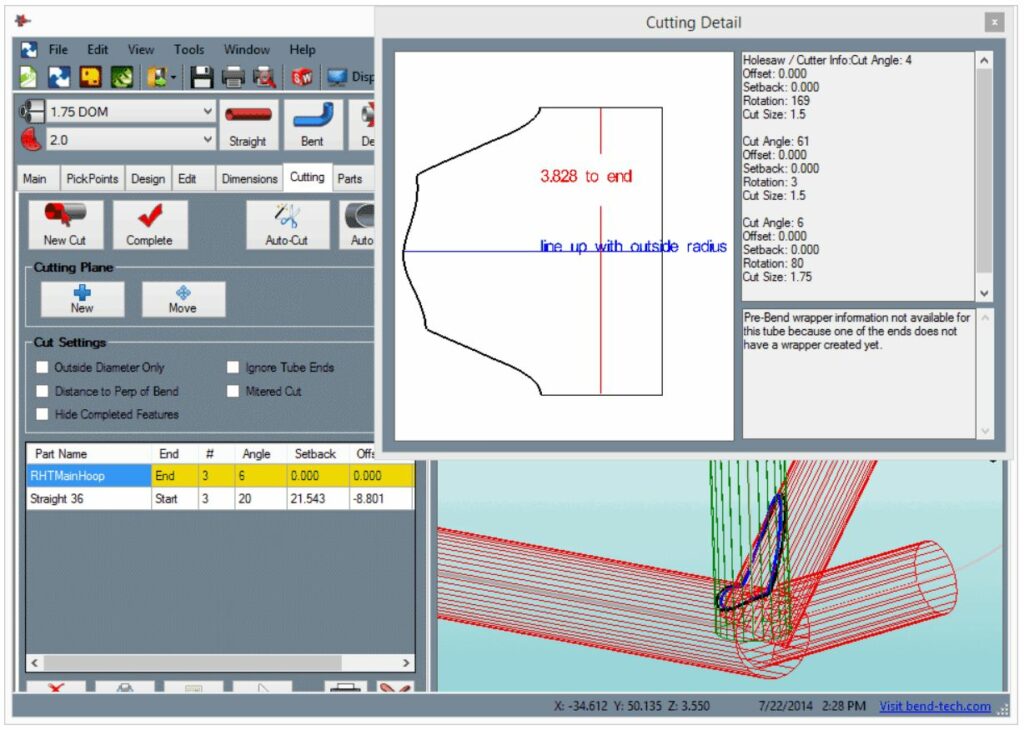
Notching templates for your holesaw, grinder, etc.
Design and visualize in full 3D
Work with your tube bender
Get notching templates for your holesaw, grinder, etc.
Key SE Features
Designer: XYZ
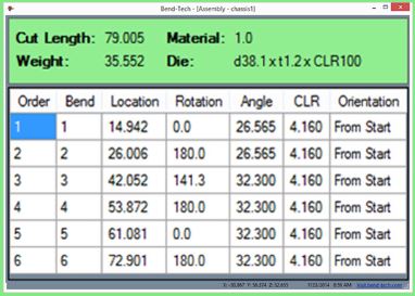
Create tube parts using an XYZ interface which consists of end points, bend locations, and center line radii. Bend-Tech software will show LRA (Length, Rotation, and Bend Angle) data as well as cut length, spring back data, and weights.
CAD Import (STEP and IGES)
Import round tubes from CAD systems. Bend-Tech works with IGES (.iges, .igs), STEP (.step, .stp), DXF (.dxf), and BREP (.brep). Send to one of the designers including XYZ or Assembly.
Advanced Calculation Output (LRA or YBC)
Location (Length), Rotation, and Angle setting format adjustments allow for a flexible output type. Includes a graphical layout screen that is a dimensioned print of the flattened tube.
Designer: Reverse Engineering
This designer allows for entry of past bending instructions and will create a Bend-Tech XYZ or LRA part model. This designer is also useful from LRA prints that are designed with the incorrect radii sizes.
Manufacturability Checking
Set restrictions for the tooling library to check for manufacturing limitations. If the part design is flagged and found to be outside the limitations then a warning button is displayed in bright red. The warning will show the problem area on the part. In the case of not having enough material at the ends, the user can select the warning field and the needed amount of material is automatically added.
Unit Conversion
Convert your tubing designs from millimeters to inches or from inches to millimeters.
Pricing Utility
Assign cost to material and hourly rates of bending & cutting times. Amortize setup time over quantity of parts needed.
1D Nesting
Find Optimized yield from current stock lengths for quantities and part lengths needed for a specific job.
Multiple Dies for Single Part
Define a part with size definitions for each individual bend.
Large Radius Bending
Create parts with large radii. Typically manufactured with a ring roll or section roller. Often used in the railing and boating industries.
Designer: Assembly Design
For customers that do not have a CAD system we have provided an interface to build an assembly. Straight parts can be added with the created bent parts to make a complete assembly.
Cutting Wrappers
Create cutting wrappers (printed paper showing the cut profile that is wrapped around the tube). The wrappers include calibration rotation and location lines for proper alignment. Bend-Tech can also provide hole saw cutting location instructions.
Designer: Panel
This feature requires Bend-Tech SM module.
Create/wrap panels between tubes in assembly.
Create radius or notches to follow the tubing.
Add holes and edit plates in Bend-Tech SM.
Centerline Adjustment
Design your part, and then adjust your parts in Inside/Outside/Center lines with click of a button.
Part Dimensioning
Dimension top, side, and front view of the part or assembly. Works great as a tool for shops to properly put together the parts in an assembly.
Spring Back Calculator
The Spring Back Calculator has an area to enter the angles of spring back experienced after bending which allows the software to automatically make the necessary adjustments. The “Results” and setup sheet have an additional column which includes the spring back angles.
Designer: Sketch 3D
Click-and-sketch part creation in 3D.
Adjustable grid-snapping.
Sketch then adjust dimensions.
Easy switching between XYZ planes.
Designer: Harpoon
Click-and-drag part creation.
Add/remove bends on-the-fly.
Intuitive drag-then-type design.
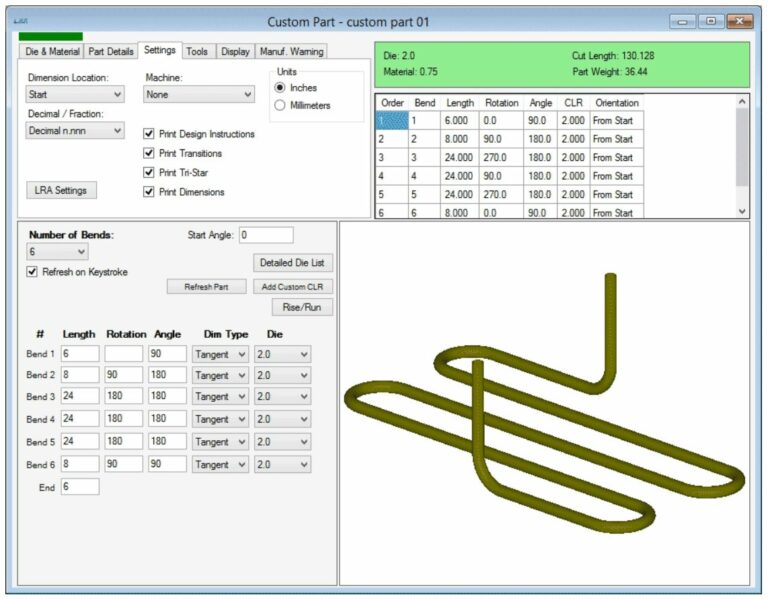
Designer: Custom Part 3D
The Custom 3D Part interface allows you to enter the definitions of your part in a sequence following the center line of the material. Directional terms are easy to understand for creation of the part. These terms are; left, right, front, back, ceiling, and floor. The bend angles and rotations are automatically calculated.
Bending Simulation
Simulation helps the fabricator visualize the bending process before running the part through the machine. This helps to confirm the manufacturability of the part and the bend order. (*Does NOT check for collision.)
Bend Order Manipulation
Bend from either end, flip the part between any of the bends, or do a custom sequencing. Verify your sequence using the Bending Simulation.
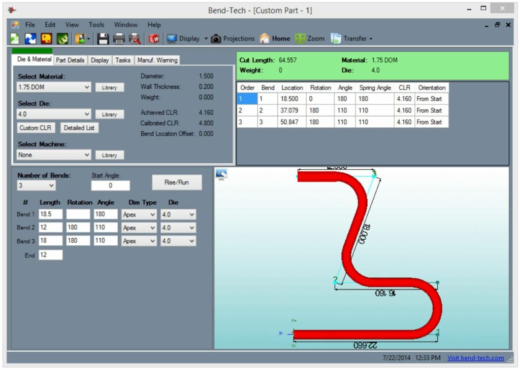
Designer: Custom Part
Create a part by starting at one end and entering the distance between bends, rotations between bends, and the angle for each bend. The length values can be apex or tangent values.
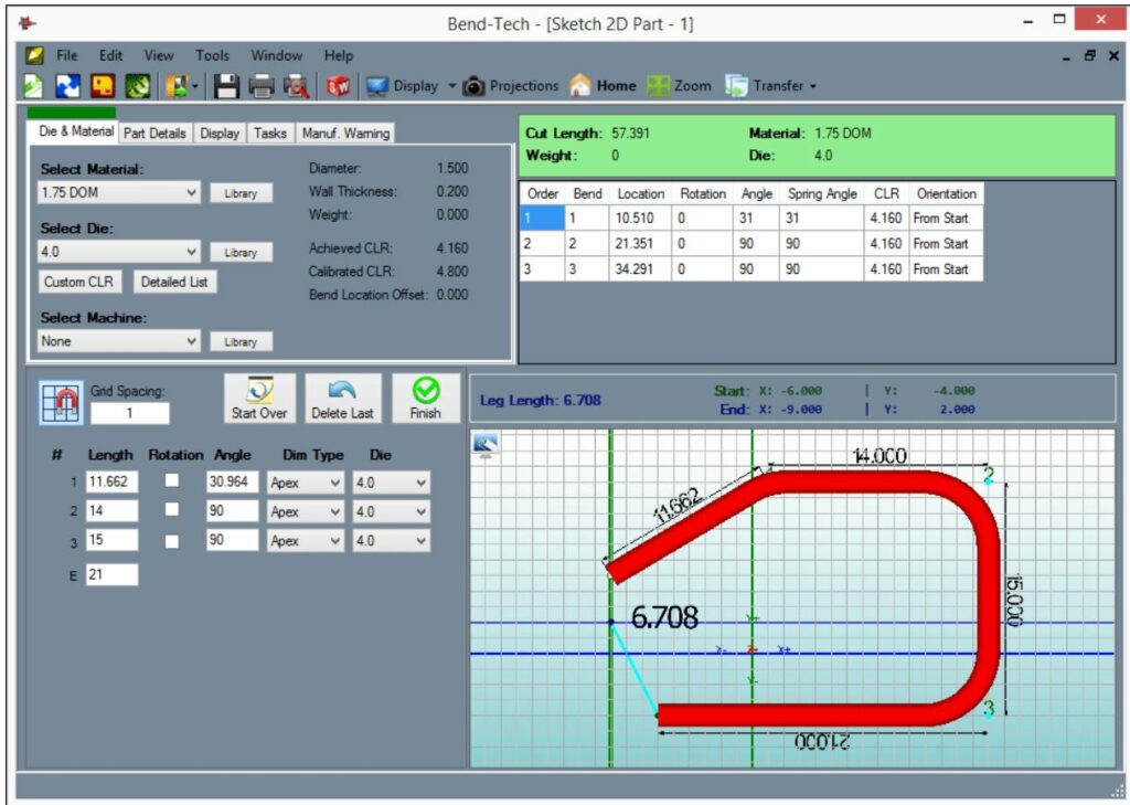
Designer: Sketch 2D
Click-and-sketch part creation.
Adjustable grid-snapping.
Sketch then adjust dimensions.
Simple, easy-to-use 2D design.
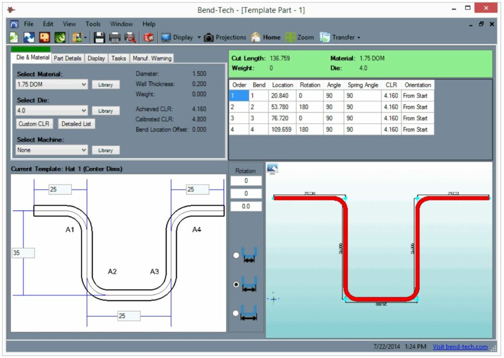
Designer: Templates
Choose from dozens of predefined templates. The templates are easy to use and in seconds you will have your design completed and be ready to start bending.
Designer: Custom Part 2D
Create a part by starting at one end and then entering in the distance between bends and the angle at each bend. The length values can be apex or tangent values. Custom Part 2D allows bends to reverse direction (180 degree rotation).
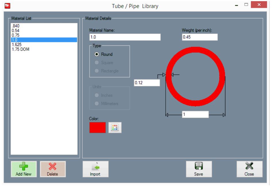
Material Library
The Material Library includes material shape, size, wall thickness, color, and weight.
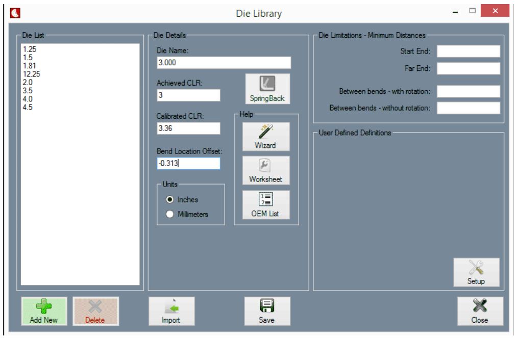
Die Library
Define your dies within the software. Definition includes CLR, Calibrated CLR (stretch factor), and Bend Location Offset.
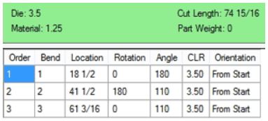
Bend Calculation Output
Software will provide cut length, bend locations, bend angles, and rotations for every parts you have designed. Each bend location is based from the end of the tube.
Post Bending Cutoff
Cutoff allows extra material to be added at the end of the tube for cutting after bending. The cut length and bend locations are automatically adjusted for cutoff values.
Bend-Tech software requires an active internet connection in order to activate the license on your computer, and then every 6 month. SE software can run offline in between. Don’t have internet connection? See Dongle Key option.
System Requirements
Minimum Requirements:
Windows Operating System (XP, Vista, 7, 8, 8.1, 10, 11). Bend-Tech software does NOT run on MAC.
1 GHz Processor
2 GB RAM (Memory)
1 GB Hard Drive Space
1024 x 768 Screen Resolution
OpenGL 1.3 Compatible Graphics Card
.NET Framework 3.5 Installed
Active Internet Connection (Internet connection is needed during the first activation and then every 6 month, software can run offline in between)
Recommended Requirements:
Windows Operating System (7, 8, 8.1, 10, 11). Bend-Tech software does NOT run on MAC.
1GHz Dual-Core Processor
4GB Ram (Memory)
1 GB Hard Drive Space
1280 x 800 Screen Resolution or greater
OpenGL 1.3 Compatible Graphics Card
.NET Framework 3.5 SP1 Installed
PDF Reader Installed (for Help Guides)
Full Keyboard and Mouse
High-Speed Internet
Please fill out the form below for more information on the Bend-Tech Dragon
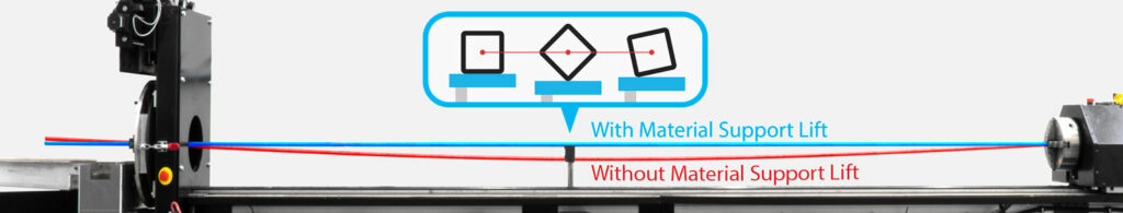
Material Support Lift (B-Axies)
The material support lift automatically moves up and down and moves out of the way from the track when not needed. The complete automation prevents the center support from colliding with the track and chuck trolley.
The fully automatic material support lift prevents bowing in long pieces (as shown in red above) for accurate cutting, marking, and engraving.
As shown above, the material support lift goes up and down to maintain constant centered leveling support as a square or rectangle tube rotates.
Tube Material Type: steel, aluminum, stainless steel, DOM, HREW, black pipe, galvanized steel, and any type of electrically conductive material.
Tube Length: full stick length capable up to 24 feet.
What is included in the purchase of a Dragon A400?
The Dragon A400 machine, center support lifter, marker, engraver, laser pointer, technology package, and Bend-Tech Dragon Software. Requirements: An active internet connection, a plasma torch with a mechanized head, 220-240V outlets, two 110-120V outlets, misc. outlets, and an air compressor. Available add-ons: plasma system, material coolant system, angle/channel motorized gate, and additional software license.
What size of plasma cutter does the machine use?
Contact our sales personnel so they can assist in selecting the correct plasma system.
What is the warranty
Your Dragon A400 has a 12 month electronics and hardware limited warranty.
What service is available for the machine?
Customer support always answers the phone during our business hours and we strive to work with you to resolve the problem. If necessary, Bend-Tech can send a Dragon Technician to location.
How does the initial setup process work?
Your Dragon A400 is shipped partially assembled. All Dragon A400 machines are fully assembled, calibrated, and tested at headquarters. Then, the machines are partially disassembled for shipping. Your Dragon A400 comes with a comprehensive assembly manual.
Are replacement parts available?
Yes, we keep a full stock of inventory of parts.
Where is the Dragon A400 made?
Your Dragon A400 is proudly assembled here in the USA. All of our departments are located in our 36,000 square foot facility in Osceola, Wisconsin. Almost all of the parts are from the Minneapolis & St. Paul area here in the Midwest.
Does the software have import, export, CAD/CAM, and designer abilities?
Yes. The Dragon CAD/CAM software can import/export to and from many of the commonly used CAD programs (such as Solidworks, Inventor, AutoCAD, PRO Engineer, Tekla, SDS2, etc.) and can be used as a design program.
What software maintenance, charges, and updates occur with the Dragon?
A 2 Year Maintenance Package is included in the purchase of a Bend-Tech Dragon A400. After the 2 Year Maintenance Package has expired, there is a year long maintenance package that is repurchased on a yearly basis to continue to receive support and software updates.
What is your current lead time?
Typically, our lead time is 2 – 4 weeks. Bend-Tech always has inventory of the A400 by constantly manufacturing machines. For the current lead time, contact our sales personnel.
Is the Dragon A400 a production machine?
Yes
How many Dragon machines are out in the field?
Over 600
How does the Dragon A400 load?
From the front, back, top, or either side; it depends on how your shop is set up and what you are cutting. There are multiple ways to easily load material. The tube can be placed in the front gate, then tightened into the self-centering four jaw chuck, and then the front gate can be closed to the correct amount of tightness on the material. Usually, loading takes one person.
What is the cut speed?
The cut speed varies based on a variety of factors; including material size, cut design, material type, tolerance requirements, material thickness, the use of a coolant system, and others. Depending on the variables, the torch can run up to 120 inches per minute while cutting. Between cutting, the rapid travel can run up to 1100 inches per minute (X-axis) and 30 RPM (Y-axis).
What is the cut quality/dross level?
The dross level varies based on a variety of factors; including amperage used, cut speed, material size, cut design, material type, tolerance requirements, and material thickness. Optional coolant circulation system can greatly improve the cut quality and dross level. You can request a benchmark/sample package to see the Dragon cut parts in person.
What is the tolerance on the cuts?
+/- 0.010” (0.254mm)
How easy is the software to use?
Like many software programs, it does take some time to get comfortable knowing the ins and outs of the Bend-Tech Software. Most people become comfortable using the Bend-Tech Software after a couple days of practice and from there they become increasingly aware of the more detailed features. In case there is confusion with certain aspects of the software, we have Wiki pages and videos to help teach and train people on the software (see more). Also, the Bend-Tech support staff is always around to help during the normal weekly business hours. There is an On-site Training option available for purchase (see more). The On-site Training includes Bend-Tech sending a Dragon Technician on-site to train your Dragon Operator(s) on how to use the machine and the software. Customers are also allowed to come visit Bend-Tech headquarters to receive their training.
How long has Bend-Tech been in the tube and pipe business?
Since 2001
Do you have more questions for us? We have a full staff of dedicated sales personnel to help answer any of your questions:
Phone: 651-257-8715
sales@bend-tech.com
Dragon A400 - Post Purchase Items
Delivery
The lead time for the Dragon A400 is typically zero to four weeks. Shipping usually takes about a week, but varies on location. Once your Dragon has started shipping, you will receive a tracking number. Contact Bend-Tech sales personnel for a current lead time.
Bend-Tech is responsible for the package through the delivery process. Bend-Tech coordinates with the shipping company and if there are any problems, Bend-Tech resolves the error with the shipping company. If there is an error or damage in the shipping, please contact the Bend-Tech sales personnel right away. The Bend-Tech sales personnel focus on making sure the necessary steps are taken to get the machine up and running as soon as possible.
The Bend-Tech Dragon A400 is shipped in a fully enclosed wood crate. The crate is 10’ (3.05m) length by 5.5’ (1.68m) width by 7’ (2.13m) height.
Installation
The Dragon A400 ships partially assembled. All Dragon A400 machines are fully assembled and calibrated at headquarters. Then, the machines are partially disassembled for shipping. Your Dragon A400 comes with a comprehensive assembly guide to instruct on how to properly reassemble the machine.
Technical Documents
The technical documents are a detailed description on all of the different aspects of the machine so that an operator can be self-sufficient in all things with your Dragon A400 machine.
Included in the technical documentation is: Customer Order, Crate Packing Checklist, Assembly Manual, Start-Up and Training Manual.
Warranty
Your Dragon A400 has a 12 month limited warranty. Defective or faulty parts identified on the machine within this time period after delivery will be replaced at no charge and shipped to the location. After the 12 month warranty period, replacement parts can be purchased through Bend-Tech, LLC. and shipped to the location at the customer’s discretion.
THE WARRANTY MAY BECOME VOID OR LIMITED IN THE EVENT THAT YOU MAKE HARDWARE CHANGES OR ADAPTATIONS TO THE MACHINE.
Dragon A400 Software Maintenance Plan
A 2 year Software Maintenance Package is included in the purchase of a Bend-Tech Dragon A400. After the 2 Year Software Maintenance Package has expired, there is a year long maintenance package that is repurchased on a yearly basis to continue to receive support and software updates. The Dragon Software is always improving to ensure the best capabilities for your company and others. The Software Maintenance Package provides consistent updates to your software and keeps you running with the newest capabilities. Your Bend-Tech, LLC. sales person will contact you one month to two weeks before your maintenance plan expires to ask if you would like to re-apply for an annual subscription.
Dragon A400 - Shop Requirements
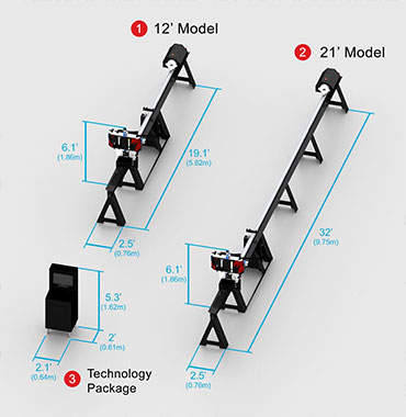
Machine Footprint
The 12’ length machine has a footprint of 19.1’ (5.82m) length by 2.5’ (0.76m) width by 6.1’ (1.86m) height.
The 24’ length machine has a footprint of 32’ (9.75m) length by 2.5’ (0.76m) width by 6.1’ (1.86m) height.
The enclosed workstation cabinet is the Technology Package is 2’ (0.61m) length by 2.1’ (0.64m) width by 5.3’ (1.62m) height and a power cord lead of 12’ (3.66m). (This is an add-on feature that does not come standard with the machine.)
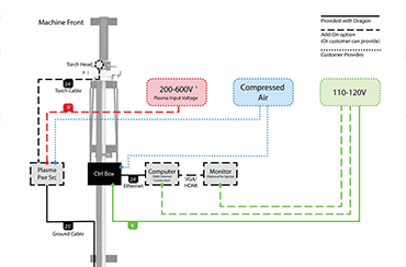
Setup Requirements
Dedicated Windows desktop or laptop with an ethernet port (The computer running your Dragon machine cannot be running other machines. Technology Package comes standard with the machine.)
Active internet connection (for the activation of your Dragon Software and to receive important updates.)
>Plasma system with mechanized head.
220-600V outlet (for plasma system)
Two to four 110-120V outlets (one for the machine, one for the laptop or computer, one if a computer monitor is being used, and one if the optional coolant system is purchased).
An air compressor or inert gas with two lines (one line for the control box and one line for the plasma system).
A250 Post Purchase Items
Delivery
The production lead time for the Dragon A250 is typically 0 to 4 weeks. Shipping usually takes about a week but varies on location. Once your Dragon has started shipping, you will receive a tracking number. Contact a Bend-Tech salesperson for a current lead time.
If needed, the Dragon A250 can be liftgate delivered and moved with a pallet jack.
Bend-Tech is responsible for the package through the delivery process. Bend-Tech coordinates with the shipping company. If there is an error or damage in the shipping, please contact the Bend-Tech service team right away. The Bend-Tech service team focuses on making sure the necessary steps are taken to get the machine up and running as soon as possible.
Installation
The Dragon A250 is shipped partially assembled in one crate. The Dragon A250 comes with instructions on the proper set up and install process.
Warranty
Your Dragon A250 has a 12-month limited warranty. Defective or faulty parts identified on the machine within this time period after delivery will be replaced at no charge and shipped to the location. After the 12-month warranty period, replacement parts can be purchased through Bend-Tech, LLC. and shipped to the location at the customer’s discretion.
THE WARRANTY MAY BECOME VOID OR LIMITED IN THE EVENT THAT YOU MAKE HARDWARE CHANGES OR ADAPTATIONS TO THE MACHINE.
Dragon A250 Software Maintenance Plan:
Included with the purchase of your Dragon, the 2-Year Maintenance Package has the latest updates and enhancements in the software and direct customer support over the phone, email, or computer.
The Next Step Towards Owning a Dragon
In Person
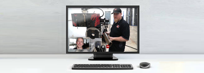
Call or email Bend-Tech to set up a time to come visit us to see the Dragon and Bend-Tech Software in person. We always welcome people to tour our facilities and receive detailed information from our Dragon Technicians through live demonstrations. If you cannot visit us in person, we can give a virtual tour of our facilities with an online video chat.
Benchmark
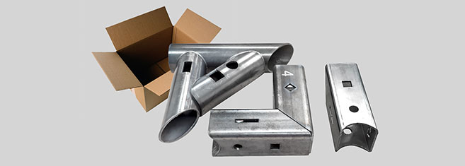
Contact us and we will make a benchmark of your parts. Send us the material and the design file, and we will cut out the parts and ship them to you with a video link of your parts being cut via email. The benchmark provides an opportunity to see the cut speed, cut quality, and clean up amount for your parts.
Virtual Cutting Demonstration
Call or email Bend-Tech to set up a time to connect with us online via live video. Our sales staff and Dragon Technicians will demonstrate the Dragon’s operation live and answer any of your questions.
Sample Package
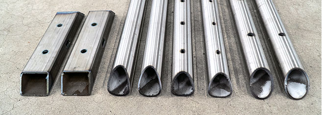
Bend-Tech can send you a sample package containing a variety of sample parts cut on the Dragon. Round, square, steel, and aluminum tubes have various cuts that show the Dragon’s cut quality (the sample pack is free including shipping).
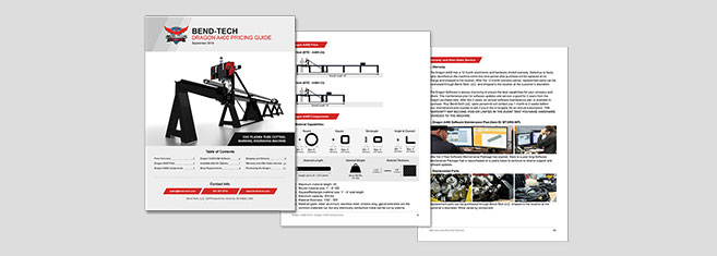
Comprehensive Pricing Guide
Contact Bend-Tech for a comprehensive pricing sheet. The pricing sheet breaks down the price on each available item. This allows you to select the best options that fits your shop’s needs.
Active internet connection, for the activation of your Dragon Software and to receive important updates.
220-600V outlet for plasma system.
Two to four 110-120V outlets. One for the machine, one for the laptop or computer, one if a computer monitor is being used, and one if the optional coolant system is purchased.
An air compressor or inert gas with one line, for the plasma system.
Dragon A250 - Frequently Asked Questions
What is included in the purchase of a Dragon A250?
The Dragon A250 machine, marker, laser light, and the Bend-Tech Dragon Software Suite.
How does the initial setup process work?
Your Dragon A250 is shipped partially assembled and comes with a comprehensive assembly manual to instruct on how to properly reassemble the machine.
Are replacement parts available?
Yes, we keep a full stock inventory of parts.
Where is the Dragon A250 made?
The Dragon A250 is proudly designed, manufactured, and assembled in Osceola, WI, USA.
Is the CAD/CAM software included?
Yes, the Bend-Tech Dragon Software Suite is included with your Dragon A250.
How many Dragon machines are out in the field?
Over 600 and counting.
How does the Dragon A250 load?
From the front, back, top, or either side; it depends on how your shop is set up and what you are cutting there are multiple ways to easily load material. The tube can be placed in the front gate, then tightened into the self-centering three jaw chuck, and then the front gate can be closed to the correct amount of tightness on the material. Usually, loading is done by one person.
What is the cut tolerance on the Dragon A250?
+/- 0.010 inch
What is the cut quality/dross level?
The dross level varies based on a variety of factors; including amperage used, cut speed, material size, cut design, material type, tolerance requirements, and material thickness. The optional Material Coolant System add-on can greatly improve the cut quality and dross level. You can request a benchmark/sample package to see Dragon cut parts in person.
Do you have more questions for us? We have a full staff of dedicated sales personnel to help answer any of your questions:
Phone: 651-257-8715
sales@bend-tech.com
Security Dongle
If a valid internet connection is not available on your computer, you may choose to purchase a security dongle to use the software offline. This will allow your computer to run Bend-Tech software as long as the security dongle is plugged into an available USB port on the computer. This USB security dongle becomes the license for your software.
Important
While the security dongle will allow your computer to run Bend-Tech software without an internet connection, there are a few drawbacks to using the offline method. Bend-Tech software will not be able to automatically download any new updates and the direct Help Session will not be available. Also, any maintenance of a security dongle requires shipment back to our facility and back to you at additional cost. If you are unable to provide shipment of your security dongle (such as loss or theft), you will be required to purchase the dongle along with the full price of your software.


")